3 installing the camera, 4 cooling circuit, 3 installing the camera 6.1.4 cooling circuit – Videotec NXW User Manual
Page 8
EN - English - I
nstruc
tions manual
6
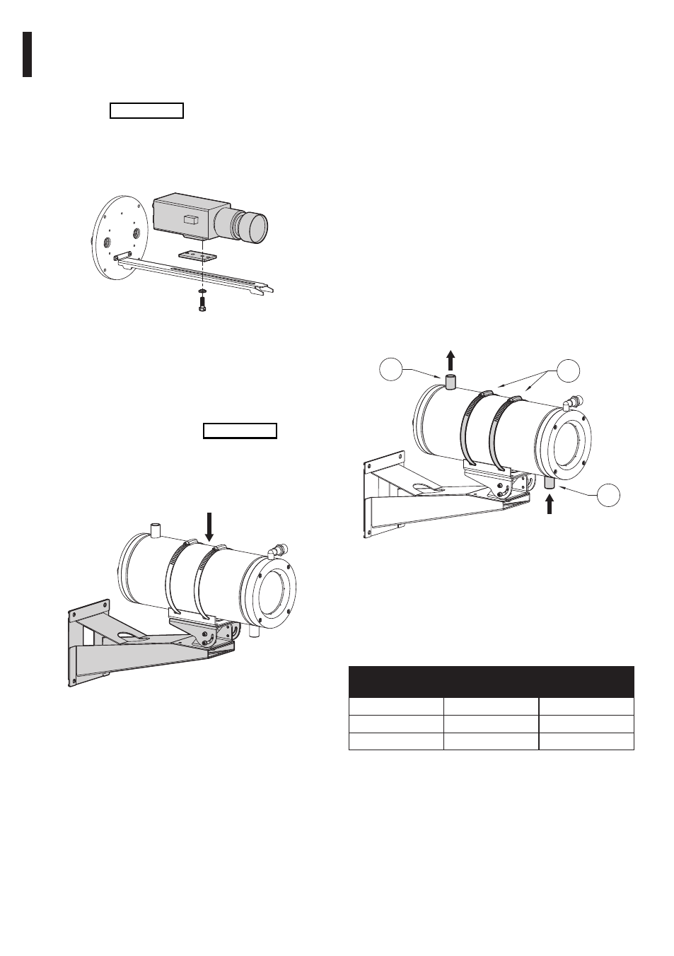
6.1.4 Cooling circuit
This section describes how to connect the
housing to the water cooling circuit and gives
the results of experimental data to determine
the dimensions of the latter. The housing is
equipped with 1/2”Gas, threaded, cooling
water inlet and outlet connectors with.
Use the connector on the housing body near the
front (01) as the cooling water inlet and the connector
near the back (02) as the cooling water outlet.
This is only a general indication since the direction
from which the heat source originates and
installation constraints may make it necessary to
adapt the position of the water connectors and
the choice of input and output according to the
specific installation. This is possible because the
housing body can be rotated with respect to the
support base by adjusting the locking ties (03).
01
02
03
OUT water 1/2“Gas
IN water 1/2”Gas
Fig. 07
The following experimental data give the water
flow rate required to maintain a temperature
below 45°C inside the housing with an external
temperature Tmax =400 °C and refer to the
use of water as cooling liquid with an input
temperature to the housing of 20°C.
T
environment
[°C]
WATER FLOW
RATE [L/MIN]
T
inside
housing
[°C]
200
2
32
300
2.2
41
400
6.5
44
Tab. 01
6.1.3 Installing the camera
This section describes how to install
the camera inside the housing.
Open the housing following the instructions
given above (Fig. 04, page 5).
Attach the camera to the internal slide with the 1/4”W
screw using the insulating bush. If necessary use the
spacers supplied and the appropriate 1/4”W screws
so as to position the camera and lens correctly.
Fig. 05
Make the correct electrical connections for
the camera and lens, passing the cables
through the cable glands. Make sure the
latter are firmly locked in place.
Close the housing by proceeding in the reverse
order to that described above (Fig. 04, page 5). Make
sure the sealing ring on the rear flange is correctly
inserted in its seating so as not to damage it.
Attach the housing to the bracket if this
has not been assembled already.
Fig. 06