Removing the unit, Connector function guide – Kenwood DNX5280BT User Manual
Page 27
27
DNX7280BT/DNX5280BT/DNX4280BT/DNX5580BT
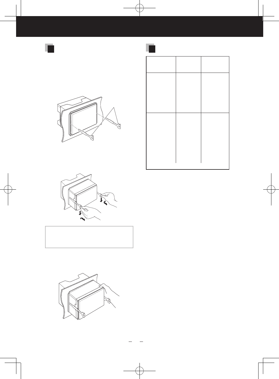
Removing the unit
1) Remove the hard rubber frame by
referring to step 1 in "Removing
the hard rubber frame" (P.26).
2) Insert the two removal tools
(accessory 4) deeply into the
slots on each side, as shown.
4
3) Lower the removal tool toward
the bottom, and pull out the unit
halfway while pressing towards
the inside.
NOTE
• Be careful to avoid injury from the catch
pins on the removal tool.
4) Pull the unit all the way out with
your hands, being careful not to
drop it.
Connector Function Guide
Pin Numbers
for ISO
Connectors
Cable Color Functions
External Power
Connector
A-4
Yellow
Battery
A-5
Blue/White
Power Control
A-6
Orange/White Dimmer
A-7
Red
Ignition (ACC)
A-8
Black
Earth (Ground)
Connection
Speaker
Connector
B-1
Purple
Rear Right (+)
B-2
Purple/Black
Rear Right (–)
B-3
Gray
Front Right (+)
B-4
Gray/Black
Front Right (–)
B-5
White
Front Left (+)
B-6
White/Black
Front Left (–)
B-7
Green
Rear Left (+)
B-8
Green/Black
Rear Left (–)
*Speaker Impedance: 4-8 Ω
B59-2048-00_00_DNX7_E_en.indd 27
10/12/16 12:11