Ii. system components, Motherboard mounting, Panel connections – Asus AP100 User Manual
Page 16: Ii. components motherboard / panel, Motherboard screw locations, Motherboard panel connector
16
AP100 Hardware Reference Guide
II. System Components
II. Components
Motherboard / Panel
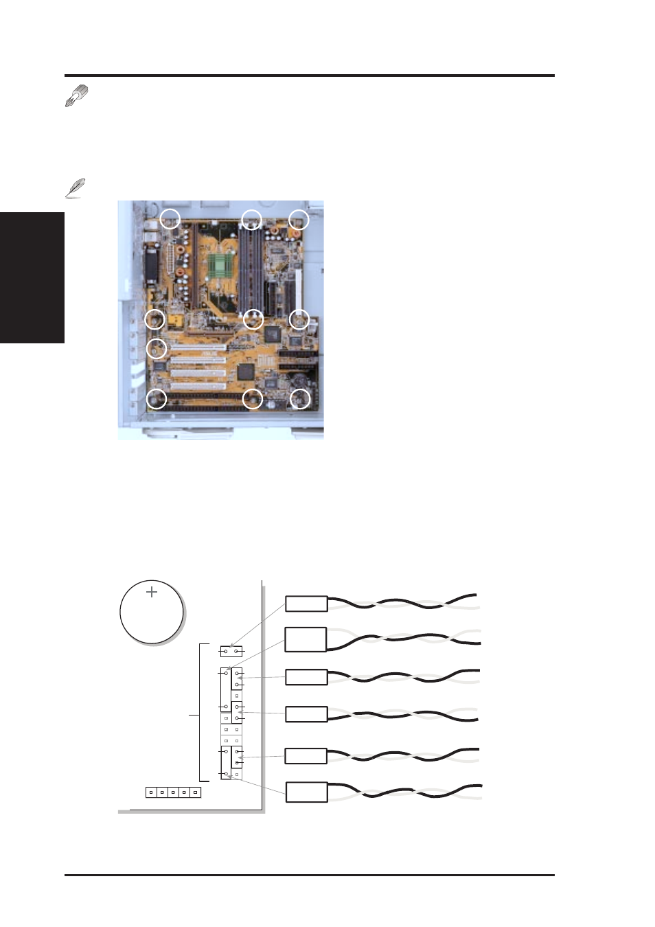
Motherboard Mounting
Once the stabilizing link bar is removed, you can install or replace the moth-
erboard but note the screw locations. All screws are necessary to provide
the needed stabilization to support all the motherboard expansion items.
NOTE:
The screw locations will vary with different motherboards.
Motherboard screw locations
Panel Connections
Several wires should be connected to the motherboard for the IDE/SCSI
activity, power, and message indicators on the front panel. Panel connec-
tions also allow for an ATX power button, reset switch, and speaker. Con-
nect the chassis front panel wires as illustrated:
H.D.D. LED
White
Red (+)
Power SW
Black
Red (+)
Turbo LED
Yellow (+)
White
White (+)
Black
Speaker
Connector for Optional Infrared Module
Button Cell Battery
for motherboard
BIOS and clock
Chassis Panel
Connectors
Reset SW
Violet (+)
White
Power LED
White
Green (+)
White
Yellow
White
Green
Red
Black
White
Violet
White
Red
Black
White
Motherboard panel connector