Led indicators – ADTRAN NT1 ACE4 User Manual
Page 18
NT1 ACE
4
User Manual
2
NT1 ACE
4
User Manual
61200242L1-1
The U interface complies with ANSI T1.601 and ITU-
T1.430 Recommendation Standard. The S/T interface com-
plies with ANSI T1.605 and ETSI ETS 300012 Standard.
The ADTRAN NT1 ACE
4
is a stand-alone unit and is pow-
ered by an external power supply (the ADTRAN power
supply, part number 336012VUR01).
LED Indicators
Table 1-1 describes the status of the LEDs located on the
front panel of the NT1 ACE
4
. There is a READY and
ERROR
indicator for each port of the NT1 ACE
4
.
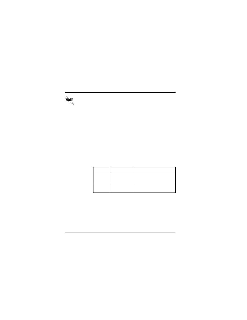
Table 1-1. Status Indicators
If an ERROR indicator is illuminated, check the flash rate of
the READY indicator to determine the source of the error. A
faster 8 Hz flash rate (8 flashes per second) indicates a net-
work problem. A slower 1 Hz flash rate (1 flash per second)
indicates an S/T interface problem.
LED
Color
Description
READY
Green
S/T and U interfaces are
ready to place call.
ERROR
Red
S/T or U interface not
ready.