Atr7040, Application circuit, Electrical characteristics – Atmel 5.8 GHz WDCT Power Amplifier ATR7040 User Manual
Page 5
5
4868C–DECT–05/06
ATR7040
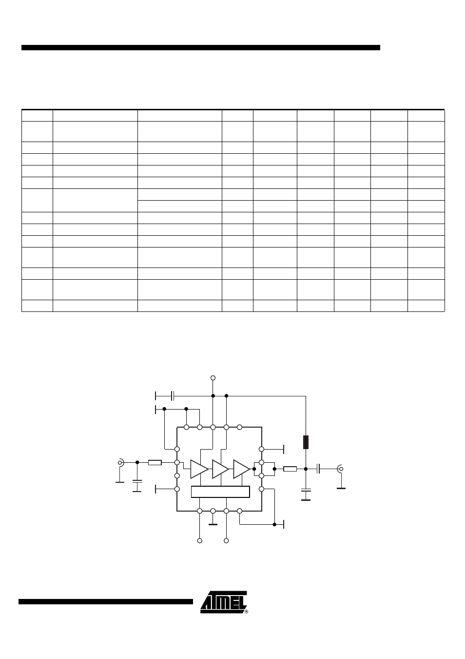
7.
Application Circuit
Figure 7-1.
Application Circuit
6.
Electrical Characteristics
Operating conditions: V
CC
= 3.6V, V
ctl
= 1.5V, input frequency = 5.8 GHz, input power 0 dBm, pulsed mode, duty cycle 10%, t
on
= 1 ms,
T
amb
= 25°C, unless otherwise specified.
No.
Parameters
Test Conditions
Pin
Symbol
Min.
Typ.
Max.
Unit
1.0
Frequency range
Depends on external
circuitry
5100
5900
MHz
1.1
Supply voltage
V
cc
2.7
3.6
3.8
V
1.2
Input power
P
in
0
dBm
1.3
Saturated power output
P
sat
25
dBm
1.4
Output power deviation
P
d
–2
+2
dB
1.5
Control voltage range
PA operating mode
V
ctl
1.0
1.7
V
Power-down mode
V
ctl
0.2
V
1.6
Control input current
PA on
5
I
ctl
90
µA
1.7
Input return loss
With external matching
10
–7
–6
dB
1.8
Isolation
V
ctl
≤ 0.2V
ISO
r
33
35
dB
1.9
Power added efficiency
At power saturation,
P
in
= 0 dBm
PAE
35
%
1.10
Current consumption
For 25 dBm output power
I
cc
250
mA
1.11
Current consumption in
power-down mode
V
ctl
≤ 0.2V
I
cc
1
µA
1.12
Duty cycle of operation
At saturated output power
100
%
C1
8
4
1
2
3
9
12
11
10
7
6
5
13
14
15
16
VCC
VCTL
VCC
slug
L1
C3
C6
RFOUT
RFIN
TRL2
TRL1
C2