54 alarms & remote control, Videoswitch, 1 alarms – Videoswitch VS-200 User Manual
Page 6: 2 rs485 remote control, 3 rs232 remote control
Videoswitch
VS-Series Desktop Switchers
5
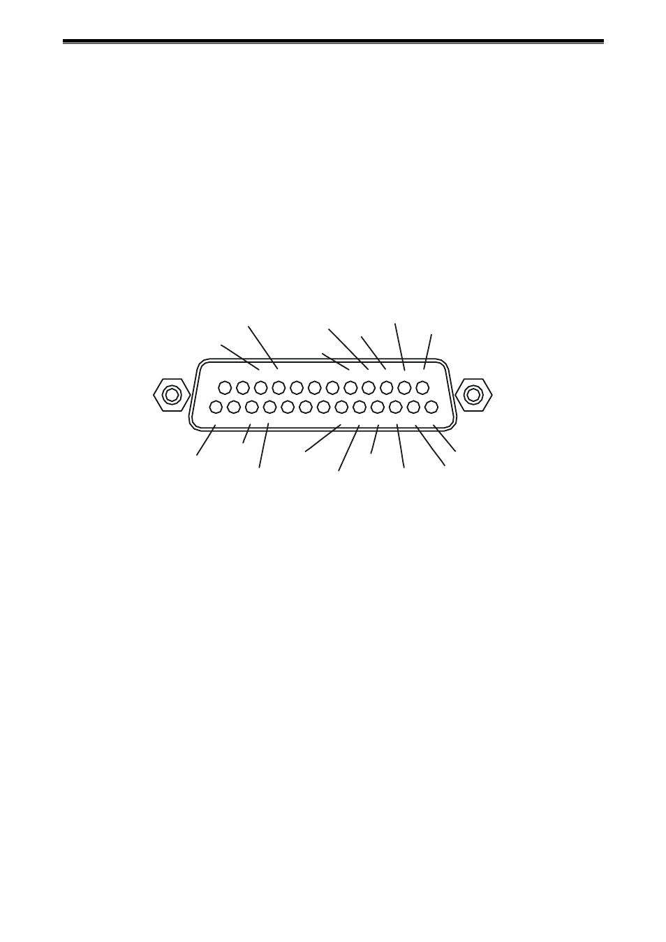
4 Alarms & Remote Control
4.1 Alarms
If alarms are required, the normally open or normally closed contacts of PIR or other detectors are
connected to the alarm connector as shown below. The default configuration is for normally open.
4.2 RS485 Remote Control
If RS485 remote control is required, the RS485 “A” and “B” signals connect as shown. Also connect TERM
to RS485 “B” to terminate.
4.3 RS232 Remote Control
If RS232 remote control is required, connect the transmit data (TXD) to the RS485 “B” pin and connect the
RS485 “A” pin to GROUND.
1
2
3
4
5
6
7
8
9 10 11 12 13
24 25
14 15 16 17 18 19 20 21 22 23
ALARM 7
ALARM 3
RELAY N/C
RELAY N/O
ALARM 8
ALARM 5
ALARM 6
ALARM 4
ALARM 1
GROUND
GROUND
RS485 “A”
RS485 “B”
TERM
ALARM 2
RELAY