21 installation, Videoswitch, 1 connecting up – Videoswitch VS-200 User Manual
Page 3: 2 termination
Videoswitch
VS-Series Desktop Switchers
2
1 Installation
1.1 Connecting Up
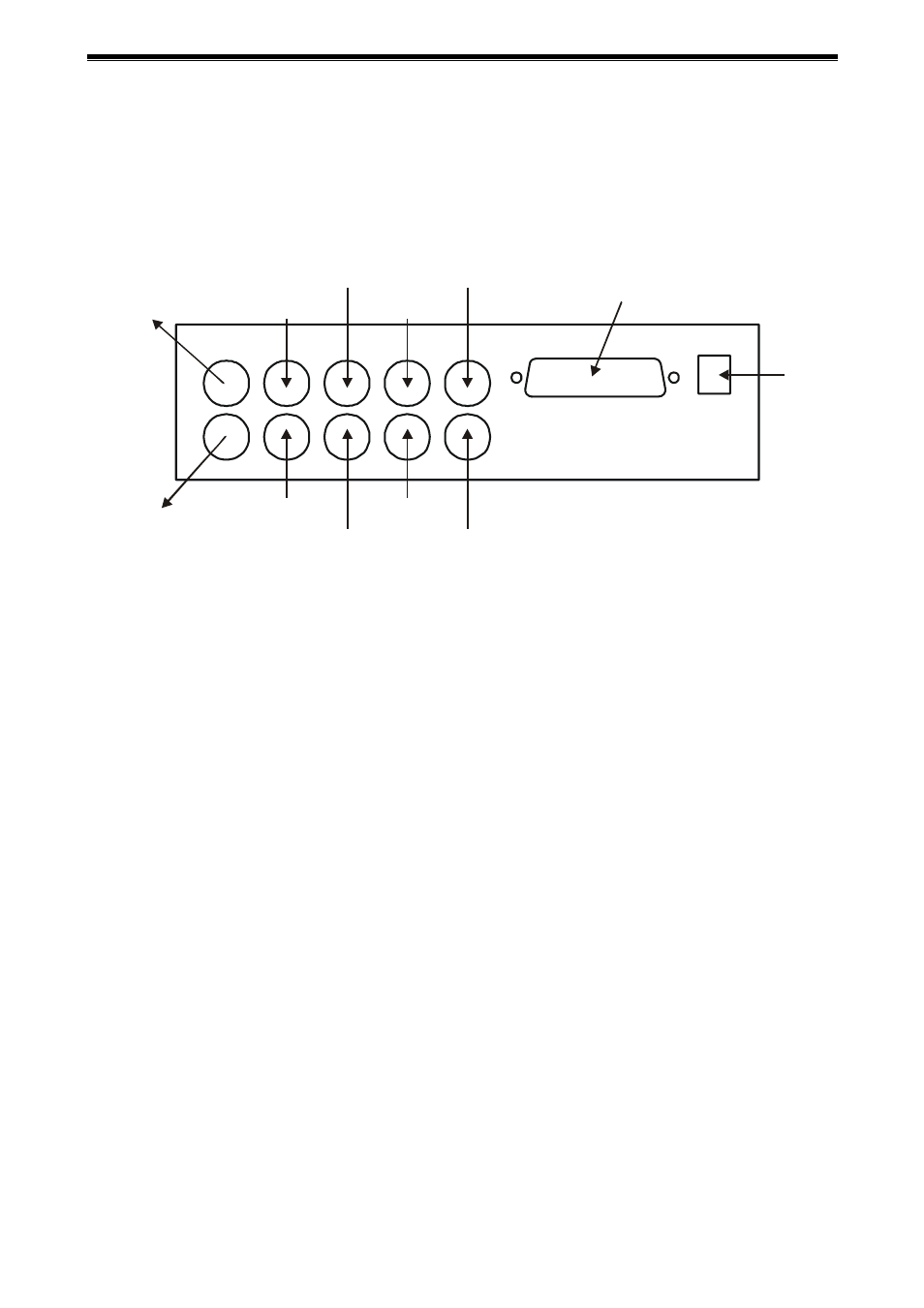
Connect cameras and monitor(s) to the BNC connectors as shown below. This diagram shows a VS-800
Series switcher. Note that on other models some of the connectors are absent.
MONITOR “A”
ALARM INPUTS & OUTPUTS
MONITOR “B”
CAMERA 1
CAMERA 2
CAMERA 6
CAMERA 5
CAMERA 3
CAMERA 4
CAMERA 8
CAMERA 7
1.2 Termination
If any camera inputs need to be un-terminated, remove the switcher’s base and carefully cut out the 75W
resistors R1 to R8 as required (Resistors R1, R2... relate to Camera1, Camera2...). Power must be off.