I -i, Voltage command connection details, Current command connection details – High Country Tek Plug Top Driver Series User Manual
Page 2
Electronic Controller Solutions for the Fluid Power Industry
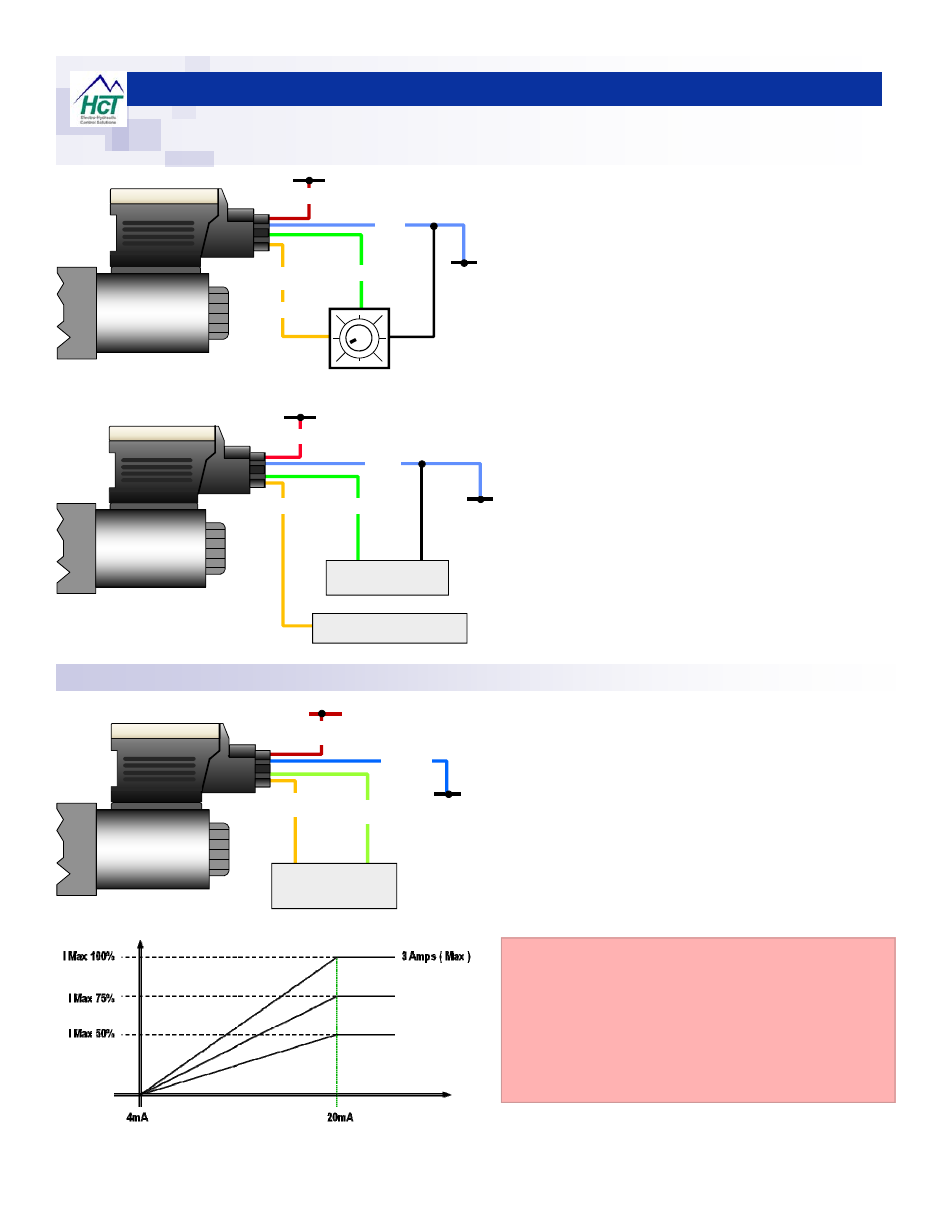
Voltage Command Connection Details:
Current Command Connection Details:
+V Supply
0VDC
10K
Potentiometer
BLUE
GREEN
YELLOW
RED
+VRef
+V Supply
0VDC
+I
-I
BLUE
GREEN
YELLOW
RED
E
xternal Signal
4-20mA
0VDC
0V
BLUE
GREEN
YELLOW
RED
+V
External Signal
0 to +10VDC
+VRef. NOT USED
Terminate Safely.
+V Supply
PTD voltage input (GREEN wire ) is internally pulled to
0V to prevent spurious operation with no command
signal connected.
Ramps DO NOT work if power is dis-connected.
Use 0-10V maximum command signal input.
Ensure external command signal source is connected to
same GND (0V) as the PTD power supply for correct
operation.
Ensure +VRef is terminated safely to avoid shorts.
Always use screened wires wherever possible.
PTD voltage input (GREEN wire ) is internally pulled to
0V to prevent spurious operation with no command
signal connected.
Ramps DO NOT work if power is dis-connected.
Use internal reference voltage +Vref for local control with
potentiometer or joystick e.t.c.
HCT recommends 10KΩ potentiometers / joysticks.
+Vref is protected and current limited to ~5mA.
12VDC PTD’s have +8VRef output.
24VDC PTD’s have +15VRef output.
Always use screened wires wherever possible.
PTD current input uses a 250Ω shunt resistor connected
to GND (0V) internally
Yellow wire (-ImA) is internally connected to GND (0v)
supply
4-20mA command is connected between +I and –I
Ramps DO NOT work if power is dis-connected.
Use 4-20mA maximum command signal input.
Always use screened wires wherever possible.
FUSES:
For clarity, no fuses are shown here.
HCT strongly recommends that the user installs a fuse
holder that if fit for purpose in the application and uses a
correctly rated fuse for each plug top driver to ensure
that damage does not occur under short circuit or wiring
circumstances.
www.hctcontrols.com