Alignment, Had product manual – High Country Tek HAD Series User Manual
Page 3
HAD Product Manual
________________________________________________________________________________
High Country Tek, Inc.
208 Gold Flat Court
Nevada City, CA, 95959.
Tel: (1) 530 265-3236
021-00141 Rev B2.1
3/8
Alignment
Turn on the power supply.
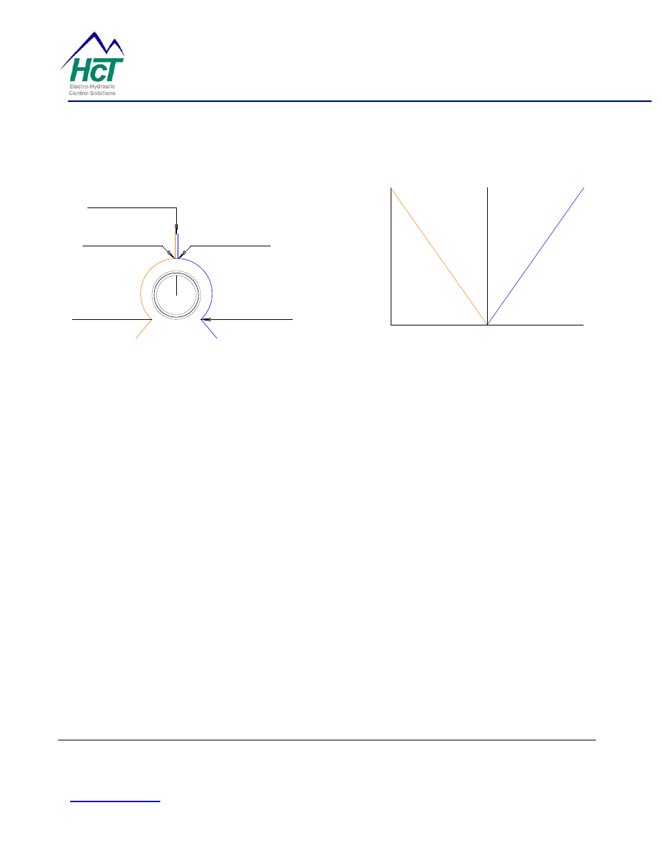
Crossover Point
(Center Pot)
Min B Coil
(< Center Pot)
Min A Coil
(> Center Pot)
MAX A Coil
(Max Pot)
MAX B Coil
(Min Pot)
Drive Coil A
Drive Coil B
100%
Coil Current
0%
Min
Max
Control Input
Drive Coil A
Drive Coil B
Crossover Adjustment
Figure, 1
CROSSOVER is the point at which the valve driver output changes between A and B coils. Only one coil will be
active at a time. The CROSSOVER pot is used to tell the valve driver what input value will cause this change. For
control inputs just above the crossover point, the output will be MIN A, and will increase to MAX for the A coil as the
control input increases. For control inputs just below the crossover point, the output will increase to MAX for the B
coil as the control input decreases. When the B LIGHT is off, the A coil will be energized and the MIN A control is
active. When the B LIGHT is on, the B coil will be energized and the MIN B control is active. Typically the crossover
point is the midpoint of the control input range. See Figure, 1 above.
1. Set the control input to the desired crossover point.
2. With the command input at the CROSSOVER point (i.e. 5 volts on a 0 – 10 volt input), if the B LIGHT is on
turn the CROSSOVER pot CW until the B LIGHT goes off. If the B LIGHT is off, turn the CROSSOVER
pot CCW until the B LIGHT goes on. Very slowly, adjust the CROSSOVER pot back and forth, observing the
midpoint of where the B LIGHT goes off and on, and set the CROSSOVER pot to this midpoint.
3. Adjust the command input for the desired minimum response point for coil “A”. Observing system response,
adjust the MIN A pot for the desired minimum current (spool shift) on COIL A. Turn the MIN A pot CW for
more current. The MIN controls are provided to allow the user to add or eliminate the valve's Deadband.
4. Adjust the command input for the desired minimum response point for coil “B”. Observing system response,
adjust the MIN B pot for the desired minimum current (spool shift) on COIL B. Turn the MIN B knob CW for
more current.
5. The MAX pot controls the maximum current (spool shift) for both the A and B coils. Set the control input to
its maximum, (20 mA, 10 V or 5 V or the high end of an external 10K pot for example) and observing system
response, adjust the MAX pot for the desired maximum COIL A current (spool shift). Turn the MAX pot CW
for more current.