ADC RS-232/V24 User Manual
Page 52
ADCP-50-304 • Issue 19 • June 1999 • Section 4: PatchSwitch X.21
Page 4-3
© 1999, ADC Telecommunications, Inc.
2.2
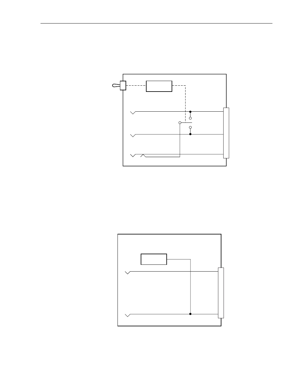
PSM-813001 X.21 PatchSwitch Module with A/B Switching and Off-Line Patch Access
This module provides monitoring and access to 15 active X.21 leads and A/B/ Switching. A
Block diagram representing the PSM-813001 module is shown in
Figure 4-2. PSM-813001 Module Block Diagram
2.3
PSM-832001 X.21 LED/Alarm PatchSwitch Interface Module
This Module provides monitoring and access to 15 active X.21 leads, LED signal status
indication, and call request and termination time-out alarming. A block diagram representing
the PSM-832001 module is shown in
Figure 4-3. PSM-832001 Module Block Diagram
SWITCHING
CIRCUIT
1629-A
ALARM
CIRCUITS
1630-A