Functional selection—conversion board -5, Functional selection—conversion board, Figure 3-3 – ADC RS-232/V24 User Manual
Page 44: 4functional selection—conversion board, Table 3-5
ADCP-50-304 • Issue 19 • June 1999 • Section 3: PatchSwitch V.35
Page 3-5
© 1999, ADC Telecommunications, Inc.
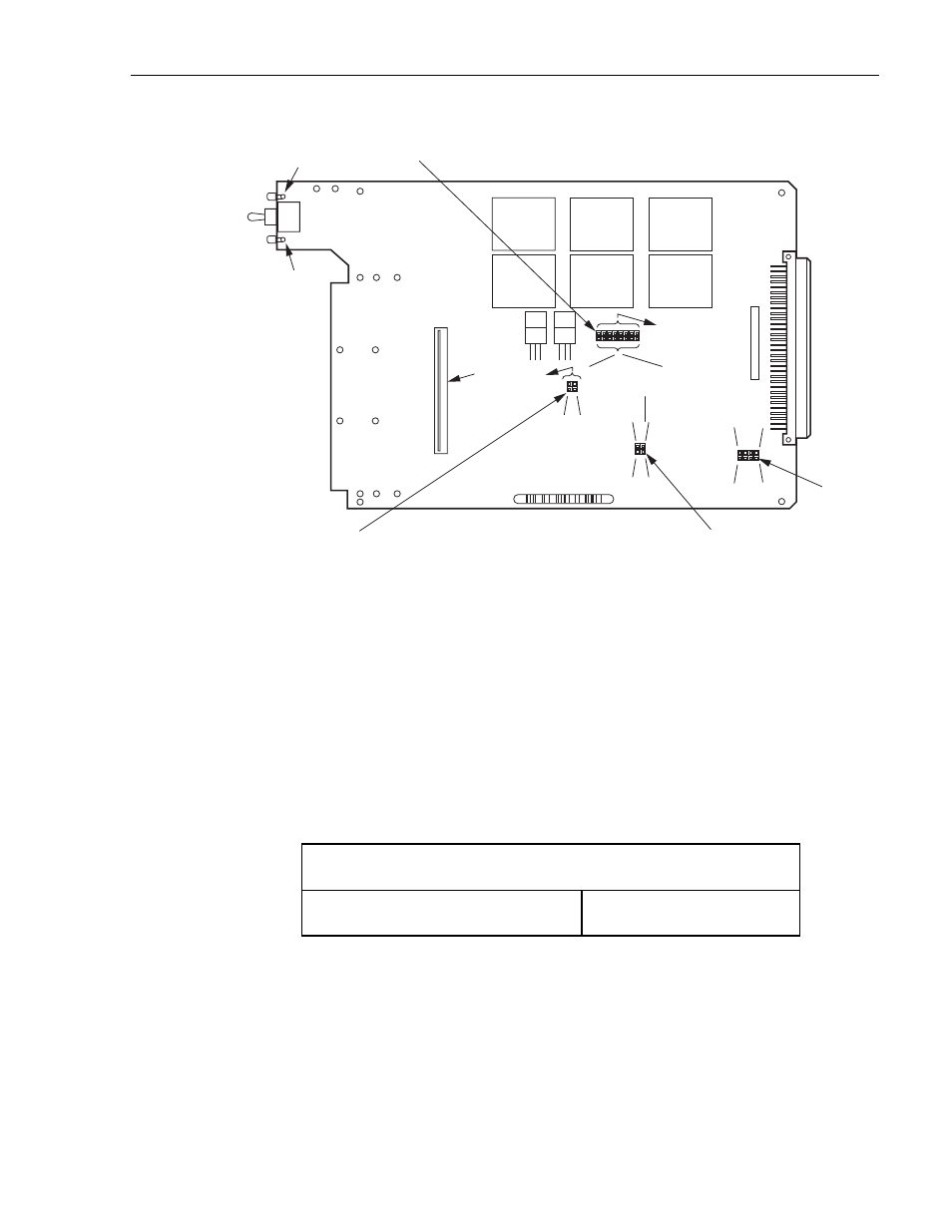
Figure 3-3. PSM-16 and PSM-17 Module PC Board (Component Side)
4
FUNCTIONAL SELECTION—CONVERSION BOARD
The item found in
is associated with the conversion board. Refer to
for item locations. The option available on the conversion board allows the user the
ability to manage the V.35 lead set. This option, as noted in
, allows the user to custom
configure the leads patched in each of his V.35 modules for his specific needs. Normal Pin
Assignments are shown in
Table 3-4. Optional Item on the Conversion Board
1.
Are any of the normally unassigned leads required by this circuit?
(See
NO
(Factory Set)
YES
TD
RD
RT
S
CTS
DCD
TC
RC
DTR
E14
E16
E18
E20
E22
E24
E26
E28
E34
E36
E44
E42
E40
E38
Y
U
AA
W
LCHD
LCHD
ALM +
ALM –
E30
E32
P1
DS1
DS2
1
22
ITEM
B
ITEM
A
ITEM
D
ITEM
C
1625-A