Rear panel – Asus Network Device CRW-3212A User Manual
Page 7
ASUS CRW-3212A User’s Manual
15
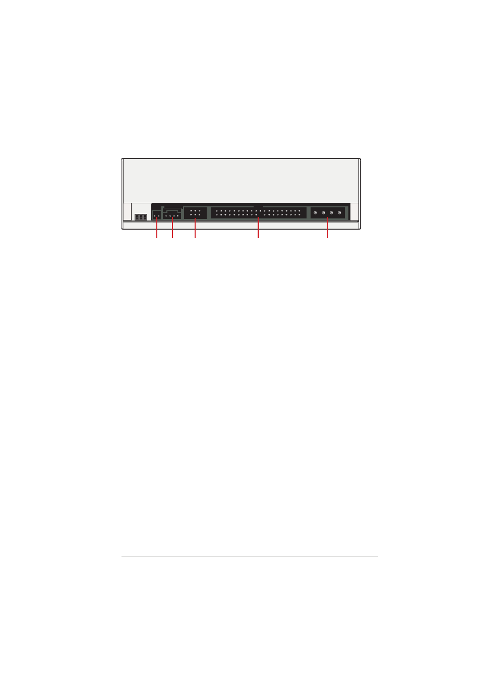
Rear Panel
1. Digital audio connector
This connector is for a digital signal output cable.
2. Analog audio connector
This connector is for an analog signal output cable.
3. Jumper terminals
These pins allow you to select either Master, Slave, or Cable Select
mode for the CD-ROM device.
4. IDE connector
This connector is for a 40-pin IDE cable to connect the drive to the IDE
interface on the motherboard.
5. Power connector
This DC connector is for a 4-pin power cable from the system power
supply.
NOTE:
The jumper pins on the leftmost part of the rear panel are
factory test pins. DO NOT cover these pins with jumper blocks.
1
3
2
4
5
See also other documents in the category Asus Hardware:
- Xonar DX (80 pages)
- Xonar DX (10 pages)
- PCI Express Audio Card Xonar DX (70 pages)
- Audio Card Xonar D2X (70 pages)
- Xonar D2X (88 pages)
- Xonar D2X (84 pages)
- D2X (88 pages)
- ROG Xonar Phoebus (72 pages)
- ROG Xonar Phoebus (122 pages)
- Xonar DSX (26 pages)
- Xonar DSX (29 pages)
- Xonar DGX (58 pages)
- Xonar DGX (38 pages)
- Xonar DGX (33 pages)
- Xonar DG (54 pages)
- Xonar DG (58 pages)
- Xonar DG (32 pages)
- Xonar DG (28 pages)
- Xonar Essence ST (52 pages)
- Xonar Essence ST (35 pages)
- Xonar Essence ST (40 pages)
- Xonar Essence ST (53 pages)
- Xonar DS (54 pages)
- Xonar DS (33 pages)
- Xonar Xense (47 pages)
- Xonar Xense (70 pages)
- Xonar Xense (45 pages)
- Xonar U3 (56 pages)
- Xonar U3 (38 pages)
- Xonar Essence STX (32 pages)
- Xonar Essence STX (49 pages)
- Xonar Essence STX (10 pages)
- XONAR D1 E4009 (72 pages)
- Xonar D1 (72 pages)
- Xonar D1 (80 pages)
- Xonar D1 (10 pages)
- Xonar Essence One (7 pages)
- Xonar Essence One (5 pages)
- Xonar HDAV 1.3 (100 pages)
- Motherboard M4A78-EM (64 pages)
- A7N8X-VM/400 (64 pages)
- K8V-XE (86 pages)
- K8V-XE (20 pages)
- M2R32-MVP (160 pages)
- M2R32-MVP (60 pages)