Features and components, Basic operation – State SUF 130 500 User Manual
Page 7
7
basic operation
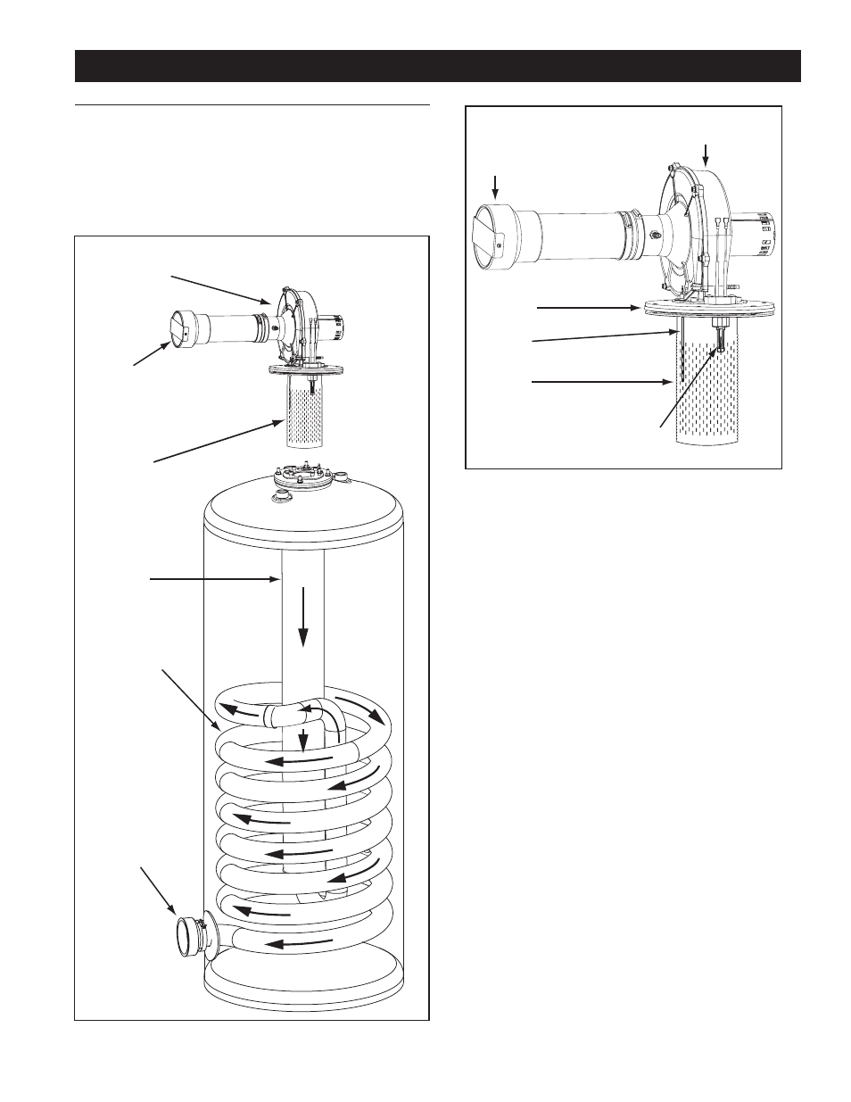
The water heaters covered in this manual have a helical coil
shaped heat exchanger that is submerged in the storage tank.
The water heater’s main Burner is a radial design burner, it
is mounted on the top and fires downward through the heat
exchanger. This is a forced draft burner; hot burning gases are
forced through the heat exchanger under pressure and exit
through the exhaust/vent connection located at the bottom of the
water heater. See Figure 1 and Figure 2.
features and components
BLOWER
BURNER
ASSEMBLY
MAIN
BURNER
(radial design)
HEAT
EXCHANGER
INTAKE AIR
(combustion air)
CONNECTION
4 INCH PVC
HELICAL
COIL
VENT (exhaust)
OUTLET
figure 1
blower/burner assembly detail
HOT SURFACE
IGNITER
COMBUSTION
BLOWER
FLAME
SENSOR
MAIN
BURNER
(radial design)
BLOWER
FLANGE
INTAKE AIR
(combustion air)
CONNECTION
4 INCH PVC
figure 2
hot surface igniter
The control system energizes the Hot Surface Igniter with 120
VAC during the igniter warm up period. When the igniter is
energized it produces sufficient heat, >1800°F (>982°C), to ignite
the main Burner.
note: Care must be taken when handling the igniter to prevent
breakage.
During the igniter warm up period prior to ignition the control
system monitors the igniter current and must sense a minimum
of 2.0 AC amps for SUF 130 300 100/101 and SUF 130 400 101
series only, and 3.1 AC amps for SUF 130 400 104 series, and
SUF 130 500 101/104 series. See the Sequence Of Operation
on page 54.
flame sensor
The control system also monitors the flame sensor to confirm
a flame is present at the main Burner. If a flame is not verified
during the ignition trial period (3-5 seconds) the control system
will immediately de-energize the 24 VAC Gas Valve. See the
Sequence Of Operation Flow Chart on page 55.