Features and components – State SBL100 199 NE User Manual
Page 7
7
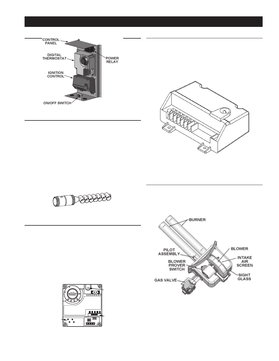
features and Components
Controls
figure 1.
the hydroCannon (self-Cleaning system)
These units include The Hydrocannon (Self-Cleaning System)
installed in the front water inlet, see Figure 2. The Hydrocannon inlet
tube can only be used in the front water inlet connection. Do not
install the Hydrocannon inlet tube in either the top or back inlet water
connection. The Hydrocannon inlet must be oriented correctly for
proper function. There is a marked range on the pipe nipple portion
of the Hydrocannon, that must be aligned with the top of the inlet
spud. A label above the jacket hole has an arrow that will point to
the marked portion of the pipe nipple if the orientation is correct.
If the arrow does not point within the marked range on the pipe
nipple, adjust the pipe nipple to correct. A pipe union is supplied
with the Hydrocannon to reduce the probability of misaligning the
Hydrocannon accidentally while tightening the connection to the
inlet water supply line. Improper orientation of the Hydrocannon can
cause poor performance of the heater and can significantly reduce
outlet water temperatures during heavy draws.
note: the hydrocannon may have 1, 3 or 7 cross tubes.
figure 2.
high limit switCh
The digital thermostat (Figure 3) contains the high limit (energy
cutout) switch. The high limit switch interrupts burner gas flow should
the water temperature reach 203°F (95°C).
In the event of high limit switch operation, the water heater cannot be
restarted unless the water temperature is reduced to approximately
120°F (49°C). The high limit reset button on the front of the control
then needs to be depressed.
Continued manual resetting of high limit control, preceded by higher
than usual water temperature is evidence of high limit switch operation.
Contact your dealer or service agent if continued high limit switch
operation occurs.
RESET
BUTTON
LED
LIGHTS
FUSE
140
130
digital thermostat
figure 3.
eleCtroniC ignition Control
each heater is equipped with an ignition control. The solid state
ignition control (Figure 4), ignites the burner by utilizing an
intermittent spark-to-pilot igniter. Spark and pilot gas ON until
lightoff or trial for ignition ends. If pilot fails to light, pilot gas and
spark OFF (100% shutoff). After 5 minutes delay, a new trial for
ignition is initiated. This sequence continues until lightoff or "Call
for Heat" is removed.
ignition Control
figure 4.
Blower/Burner assemBly
The fan-assisted combustion system includes a spark-to-pilot
ignitor, 100% premix stainless steel burners, and prejets for input
rate and precision air/gas ratio control.
Blower/Burner assemBly
figure 5.
The intake air screen is attached to the inlet of the combustion
blower. Inspect the intake air screen every six months. The intake
air screen should be cleaned of any buildup of debris or foreign
material.