State SBL100 199 NE User Manual
Page 26
26
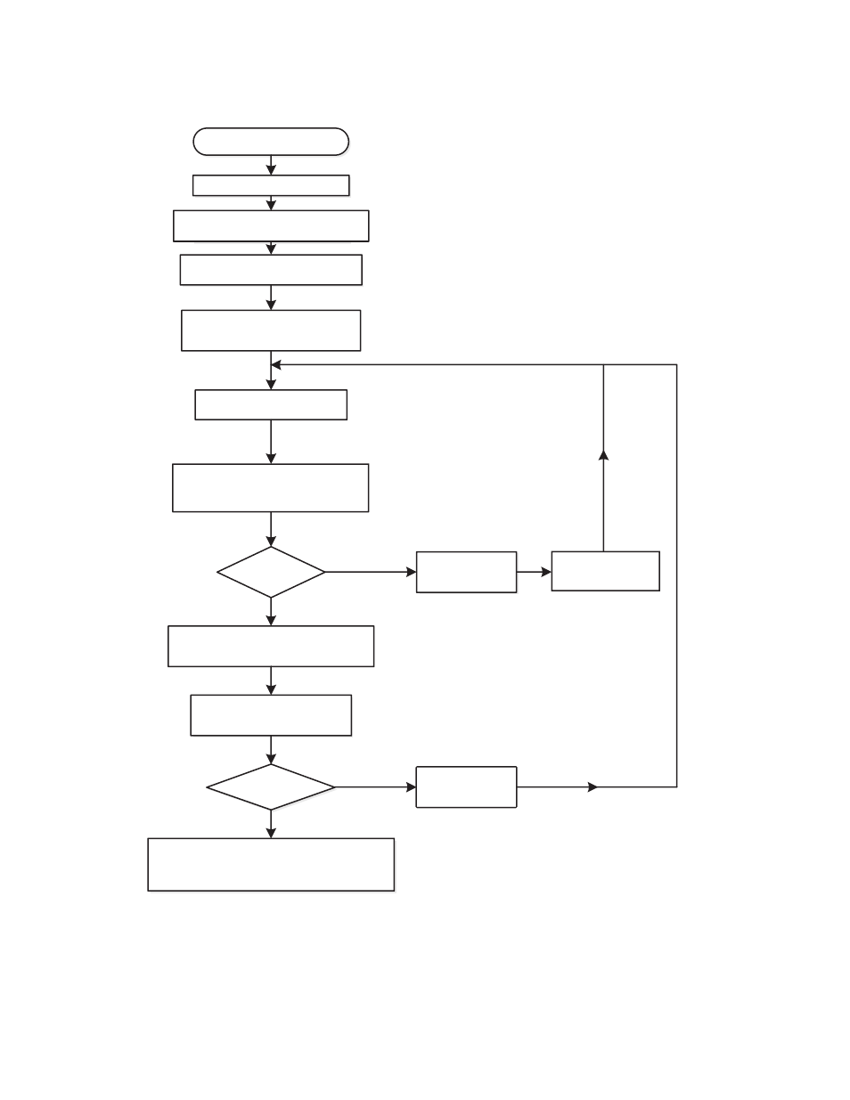
seQuenCe of operation flow Chart
Description of this flow chart can be found in the “SeqUeNCe OF OPerATION” section found on page 26.
Thermostat calls for heat
Switch power on to unit
Blower engages Prover Switch
Ignition Control monitors
flame signal
Thermostat is satisfied
Blower – off; Blower Prover – opens
Ignition Control – off; Gas Valve – closes
Loss of flame signal?
YES
YES
NO
NO
Blower power relay is energized to
start blower
IgniƟon Control provides power to Spark
Igniter and Pilot Gas Valve and monitors
Flame Sensor to determine if Burner is lit
24VAC power to the IgniƟon
Control and self check
Trial for igniƟon
Spark Off and Open main Gas Valve
5 minutes retry
delay
Close pilot gas
valve and Spark off
Flame Proved?
Close Main valve
and Pilot valve
figure 24.