Sequence of operation flow chart – State SBL85 390 NE A User Manual
Page 27
27
seQuenCe of operation flow Chart
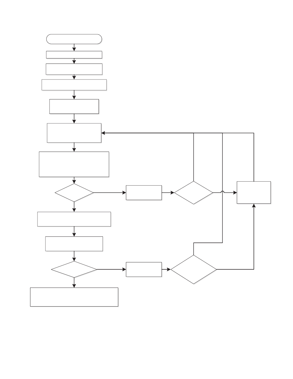
Description of this flow chart can be found in the “SequeNCe OF OPerATION” section found on page 26.
Thermostat calls for heat
Switch power on to unit
VFD sends power to Blower
Blower engages Prover Switch
Blower runs at low speed
After 30 seconds, Ignition
Control provides power to
Spark Igniter and opens Gas
Valve
Ignition Control maintains spark for up
to 4 seconds and monitors Flame
Sensor to determine if Burner is lit
Does Burner
light?
Ignition Control changes Blower from
low speed to high speed after 5 seconds
Ignition Control monitors
flame signal
Thermostat is satisfied
Blower – off; Blower Prover – opens
Ignition Control – off; Gas Valve – closes
Wait 15 minutes.
Blower runs at
low speed
Is this the third loss
of flame signal?
Is this the third
ignition trial?
Loss of flame signal?
YES
YES
NO
NO
Gas Valve – off
Gas Valve – off
NO
NO
YES
YES
figure 24.