Condensate drain line installation – State SPX 50 DHPT User Manual
Page 6
6
Please note the following:
•
The system should be installed only with piping that is
suitable for potable (drinkable) water such as copper,
CPVC, PEX or polybutylene. This water heater must
not be installed using iron piping or PVC water piping.
•
Use only pumps, valves, or fittings that are compatible
with potable water.
•
Use only full flow ball or gate valves. The use of valves
that may cause excessive restriction to water flow is
not recommended.
•
Use only 95/5 tin-antimony or other equivalent solder.
Any lead based solder must not be used.
•
Piping that has been treated with chromates, boiler
seal, or other chemicals must not be used.
•
Chemicals that may contaminate the potable water
supply must not be added to the piping system.
Connecting the Condensate Pump
Optional Overfl ow Shut Off Switch
1. Determine if you have a floor drain, if not a condensate
pump will be required.
2. Turn off power to the electrical wiring for the water
heater at the circuit breaker/fuse box.
3. Locate the white 18 AWG wire loop close to the drain
connections (Figure 5).
4. Cut the loop and strip insulation off of the two ends.
5. Measure the distance from the condensate drain pan
cover to the condensate pump, and cut two 18 AWG or
larger wires to correct length and strip the insulation at
both ends of each wire (Figure 7).
6. Remove the condensate drain pan cover by removing
the four screws, pull these two wires through the
grommet on the drain pan cover. Connect these two
wires to the two wires on the water heater using wire
nuts or other connectors. Reinstall the drain pan cover
and keep the connection joint inside of the cover.
7. Connect the free ends of the two wires to the shut off
switch on the condensate pump in accordance with the
condensate pump manufacturers recommendations
(Figure 7).
8. Turn on electrical power to the water heater.
9. S
elect the efficiency mode. After about 8 minutes
(the user interface module will display “-”, “--”, “---”
repetitively during this period), the heat pump will turn
on if the ambient temperature and water temperature
meet the heat pump requirement.
10. Test the operation of the shut off switch by unplugging
the condensate pump and filling the condensate
reservoir with water until the float switch opens the
circuit.
11. The heat pump should turn off and the error code “EoF”
will appear on the display screen.
12. Plug the condensate pump in and verify that the pump
operates and pumps the water out of the condensate
reservoir.
13. The error code on the display should clear and the heat
pump should operate after 8 minutes.
Condensate Drain Line Installation
The condensate drain lines consist of one 3/4" PVC line as
the primary condensate drain line and one 1/2" clear rubber
tubing for the condensate over flow. These condensate
lines are located on the upper right rear section of your
water heater. The lines should terminate a maximum of
six inches above an adequate drain. Do not discharge
the condensate drain lines into the metal drain pan. If no
floor drain is available or the drain is above the level of the
condensate line, a condensate pump should be installed.
These pumps are available from local distributors.
When installing the drain line, note the following:
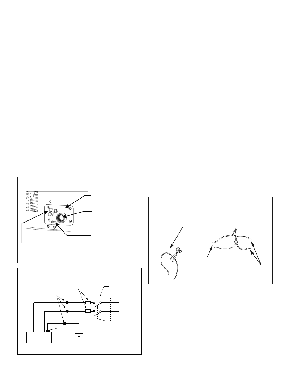
Figure 5
Condensate Pump Wiring
Overflow Slot
Main Drain Connection
Condensate Drain
Access Cover
Condensate Pump Wiring
Loop 18 AWG-White
(Loop Located Close to the Drain Connections)
Red
Black
Approved Connectors
Figure 6
Wiring Diagram
Overload
Protection
To 240v
1 Phase
Power supply
Electrical
Service ground
L1
L2
Circuit
Breaker
Ground
Wire
Green
Figure 7
Condensate Pump Wiring
Condensate Pump Wiring Loop
22 AWG - White
(Loop Located Close to the Drain Connections)
White Wires
From Water Heater
Wires to Condensate
Pump Overflow
Shut Off Switch
(22 AWG or Larger)