Figure 12 – Outback Power Systems MATE Serial Communications Guide User Manual
Page 13
Mate Serial Communication Guide
Copyright 2007
© OutBack Power Systems, Inc.
19009 62
nd
Ave NE, Arlington WA 98223 USA
Page 13
of 20
Rev 4.04 10/21/08 Tel 360 435 6030 Fax 360 435 6019
MX60 Aux mode: ‘00’ to ‘99’ This shows what Aux output mode is being
run on the MX. Refer to MX manual for mode descriptions. FLEXmax 80
or FLEXmax 60 the lower 6 bits represent the programmed Aux mode. If
bit 7 is set (data greater than 63) then Aux mode is active.
Error modes: MX60 Error modes are implemented for MX versions greater than 5.11 and FLEXmax 80
and FlexMAX 60.
Error modes: ‘000’ to ‘255’ This is an ASCII expression of an 8 bit byte, with each bit representing a
different error. Referring to Figure 11, a returned ‘032’ would be shorted battery sensor.
BIT # Value Warning
1 1
unused
2 2
unused
3 4
unused
4 8
unused
5 16
unused
6
32 Shorted Battery Sensor
7 64
Too
Hot
8 128
High
VOC
Figure 11
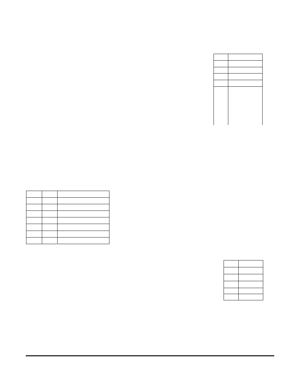
MX/FM Charge mode: ’00’ to ‘99’ This data represents the MXs charger mode.
See Figure 12.
Battery Voltage: ‘000’ to ‘999’, A 24.8 Vdc battery voltage will be sent as ‘248’.
*Daily AH: ‘0000’ to ‘2000’, (FLEXmax 80 and FLEXmax 60 only) Running daily total of amp hours
produced by the charge controller. ‘9999’ is returned if charge controller is MX60
*On FLEXmax 80 and FLEXmax 60 this number is reset at midnight if connected to MATE.
DATA MODE
"00" Disabled
"01" Diversion
"02" Remote
"03" Manual
"04" Vent
Fan
"05" PV
Trigger
“06”* Float
“07”* ERROR
Output
“08”* Night
Light
“09”* PWM
Diversion
“10”* Low
Battery
*FM80/FM60
Figure 10
DATA MODE
"00" Silent
"01" Float
"02" Bulk
"03" Absorb
“04” EQ
Figure 12