Part replacement instructions, Replacement of the pcba module – Outback Power Systems Radian Series Inverter/Charger Service Instructions User Manual
Page 3
Part Replacement Instructions
900-0128-01-00 Rev C
3
Replacement of the PCBA Module
IMPORTANT: MATE3 Upgrade
When replacing the PCBA Module, make certain to upgrade the MATE3 firmware to the
latest revision. If it is not upgraded, the MATE3 may not recognize any new inverter
functions. This will make them inaccessible to the user. See the OutBack website,
www.outbackpower.com, for the latest firmware revisions.
Tools
Flat screwdriver with small head (4 mm wide or less)
Socket wrench with 8-inch extension and 10 mm socket
Procedure
To replace the PCBA Module:
1.
Disconnect all connections to the Auxiliary terminals, MATE3, and RTS connectors. The connection to the MATE3 is
labeled “Remote” on the control board. The connection to the RTS is labeled “Battery Temp” on the control board.
2.
Disconnect the external AC input and output wiring by unlocking the tabs on the terminal block (pulling them to a
perpendicular position so that they stand out from the board). Unlocking each tab releases the tension on the wire.
Pull the wires free from the terminals.
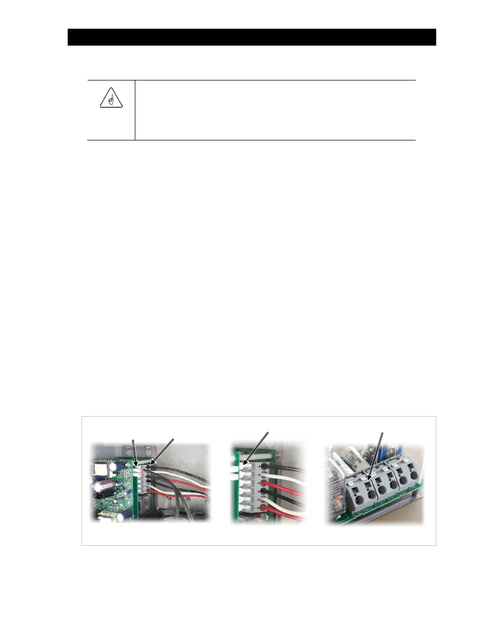
3.
The Power Module may have either four or six transformer wires connected to the PCBA Module, depending on
Radian model (see image A in Figure 3). Additionally, the Radian models use different types of terminal blocks to
secure the transformer wires.
Note the locations of the wires for later reference. If possible, take a photograph of the wire placement prior to
disconnection. For some Radian models the type of terminal block shows markings on the terminal blocks
(L1=Black, L2=Red, N=Neutral) and below them on the circuit board (RIGHT XFMR, LEFT XFMR and NEUTRALS) that
identify the correct connections. For other Radian models there are only markings on the circuit board (L2-L, NEU-L,
L1-L, L2-R, NEU-R, L1-R) that identify the correct connections. Refer to Table 1 for model-specific locations of the
transformer wires, fan wires and ribbon cables.
NOTE: Models with only four wires do not have L2 connections or any NEUTRALS circuit board marking.
4.
Disconnect these wires by one of two methods, depending on the type of terminal strip. If the terminal strip has
locking tabs, unlock them just as in Step 2. (See image B in Figure 3.) Pull the wires free from the terminals.
If the terminal block does not have locking tabs, insert the screwdriver horizontally into the terminal block slot for
each wire. Lever the screwdriver outward (from the back of the housing to the front). This releases the tension on
the wires. Pull the wires free from the terminals. (See image C in Figure 3.)
Figure 3
Transformer and Fan Terminals
5.
Disconnect the fan wires by pinching their connectors and pulling to the right. Note the text on the circuit board
that shows the correct connections (FAN RIGHT and FAN LEFT).
Transformer
Terminals
Fan Terminals
(x2)
A
B
C
Tab
Slot