Warning, Installation in wood stud wall a, Fig. a.1 – Monoprice 6518 Recessed Wall Mount Bracket User Manual
Page 4: Installation in wood stud wall (continued)
4 of 8
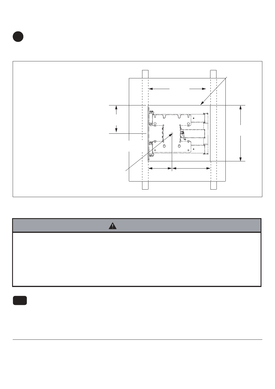
In-wall box (BB) can be installed between two studs 16" off center. Use a stud finder to locate the edges of the stud.
Use of an edge-to-edge stud finder is highly recommended. Based on its edges, draw vertical lines down in the inside
edges of stud’s. Mark desired center of screen between studs. Draw a horizontal line above desired center of screen
as indicated in figure A.1 Draw a second horizontal line 12.9" (328 mm) below this line to outline wall
opening between inside edges of studs. Remove drywall inside cut outline.
Installation in Wood Stud Wall
A
Center of adapter plate will be
located 6" (163 mm) below the
top cut line.
Note: Center of adapter plate
may not represent screen center.
Placement of in-wall box will
depend on the screen center and
location of screen mounting
holes in relation to adapter plate.
Note: Depending on right or left
side mount orientation shown in
figure A-1 in step 1.1, screen
center will be 5.51" (140 mm)
from the inside edge of stud.
Screen center with models
JHAI200:
CENTER OF
ADAPTER PLATE
PP
14.4"
(366 mm)
CENTER OF
ADAPTER PLATE
PP
TOP CUT LINE
fig. A.1
8.86"
(225 mm)
5.51"
(140 mm)
Installation in Wood Stud Wall (continued)
Installer must verify that the supporting surface will safely support the combined load of the equipment and all attached
hardware and components.
Tighten wood screws so that wall plate is firmly attached, but do not overtighten. Overtightening can damage the
screws, greatly reducing their holding power.
Make sure that mounting screws are anchored into the center of the stud. The use of an "edge to edge" stud finder is
highly recommended.
Hardware provided is for attachment of mount through standard thickness drywall or plaster into wood studs. Installers
are responsible to provide hardware for other types of mounting situations.
WARNING
In-wall box can be flipped for left of right side mount orientation as shown in figure A-1.1
Insert in-wall box (BB) into cut-out. Level in-wall box, and mark the center of the six mounting holes.
Make sure in-wall box is level, secure it using six M6X60(H) concrete anchor as shown in figure A-1.2
A-1