3iii. symbol definition and button location – Sper Scientific 800024 Thermometer 4 Channel Datalogger User Manual
Page 4
3
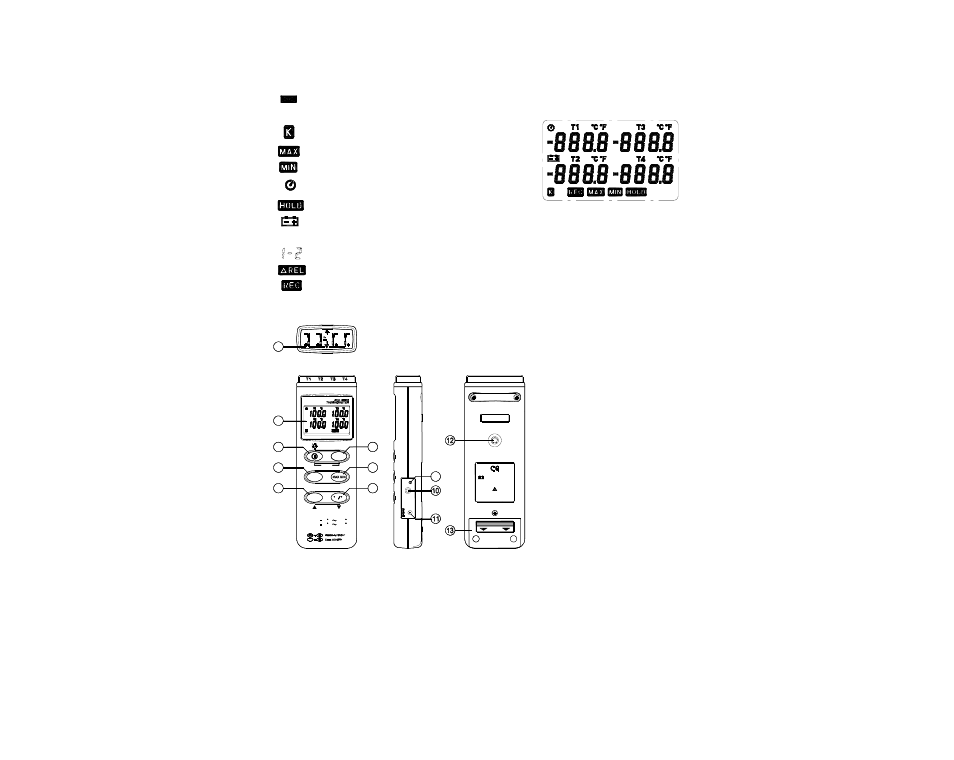
III. Symbol Definition and Button Location:
: This indicates that the minus temperature is sensed.
: Centigrade and Fahrenheit indication.
: Thermocouple Type Indication.
: The Maximum value is now being displayed.
: The Minimum value is now being displayed.
: This indicates auto power off is enabled.
: This indicates that the display data is being held.
: The Battery is not sufficient for proper operation.
T1,T2,T3,T4
: It indicates the value below is T1, T2, T3, T4 Temperature sensor.
: It indicates the value below is T1-T2 sensor.
: The reading is now under relative mode.
: This indicates that the tester is recording. If it blinks, it indicates the memory is full.
Button Location:
•
1
K type temperature sensor T1 to T4
input connector
•
2
LCD display
•
3
ON/OFF & Backlight button
•
4
Hold button
•
5
Record button
•
6
T1-T2 button
•
7
MAX MIN function control button
•
8
°C, °F control button
•
9
Offset calibration screw
•
10
Digital output connector
•
11
AC power adapter connector
•
12
Tripod connector
•
13
Battery cabinet cover
T2
24V
MAX
60V
T1
T4
T3
3
4
5
2
1
OU
T
P
U
T
DC
9
V
6
7
8
CA
L
9
MANUAL FOR SAFETY
OPEN
NEDA 1604 6F22 006P
PLEASE READ
9V BATTERY
HOLD
C
F
T1-T2
SETUP
INTV
CLOCK
2498
1370
RANGE
REC
200
328
POWER-UP OPTIONS
F
C
F
C
REC