Applica 130A Heaters User Manual
Page 9
Installation
Page 9
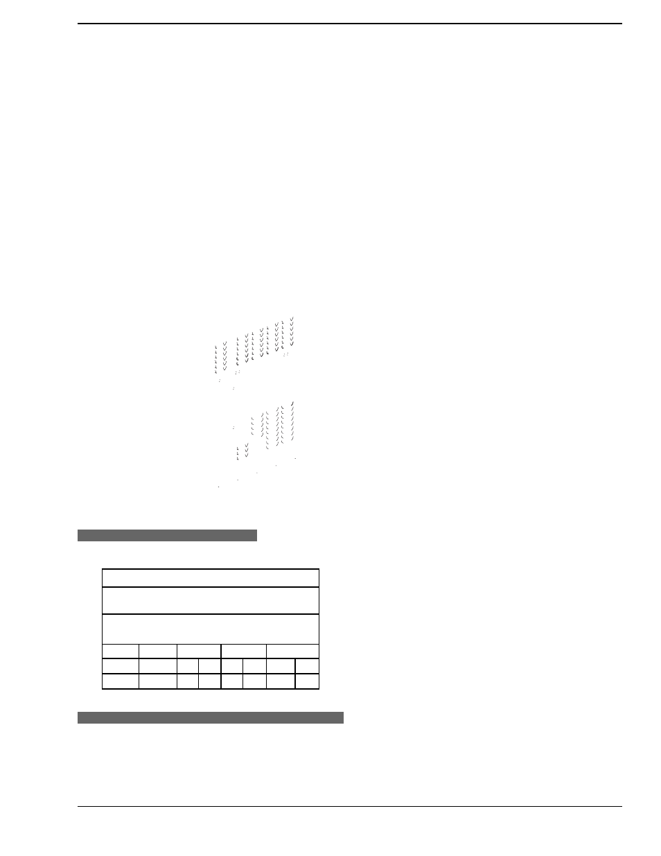
Figure 9C. Honeywell MV Gas Valve.
E
LECTRONIC
I
GNITION
G
AS
V
ALVES
Figure 10. Location of Gas Pressure Adjustment.
P
IPE
S
IZING FOR
G
AS
C
ONNECTIONS
Table 5. Maximum Equivalent Pipe Length.
W
ATER
C
ONNECTIONS
The heater requires water flow and positive pressure to
fire and operate properly. It must therefore be installed down-
stream of the discharge side of the filter pump. A typical
installation is plumbed as follows:
Maximum Equivalent Pipe Length
Natural Gas 1000 BTU/FT3 0.60
Specific Gravity @ 0.5 in. WC Pressure Drop
Propane Gas 2500 BTU/FT3 1.53
Specific Gravity @ 0.5 in. WC Pressure Drop
Input
1/2”
3/4”
1”
Model (KBTU)
N
P
N
P
N
P
130A
130
15
35
60
145
200
500