Maintenance, Service – Applica 130A Heaters User Manual
Page 16
Maintenance / Service
Page 16
MAINTENANCE
The following preventative maintenance is to be per-
formed one month after start-up and semi-annually thereafter.
1. Inspect top of heater and drafthood for soot, a sticky black
substance around finned tubes and "V" baffles, and open
flue gas passageways. Any visible soot should be cleaned
for proper operation. See the Desooting Procedure in the
Service Section.
2. Clean main burners and pilot burner of dust and lint.
3. Inspect and operate all controls, gas valve and pressure
relief valve (if equipped).
4. Make visual check of the burner and pilot flames. Flame
pattern on the main burner and pilot is illustrated in the
Post Start-Up Inspection section. Yellow flame means
restriction of the air openings. Lifting or blowing flame
indicates high gas pressure. Low flame means low gas
pressure. Should these occur, shut the heater off and con-
tact your gas supplier or qualified service agency.
5. On indoor heaters, clean room intake openings to ensure
adequate flow of combustion and ventilation air.
6. Keep area around heater clear and free from combustible
materials, gasoline and other flammable and corrosive
vapors and liquids.
SERVICE
W
ATER
P
RESSURE
S
WITCH
The water pressure switch, ensures that the heater oper-
ates only when the filter pump is in operation. It is located on
the In/Out header. It is factory set at 1.75 PSI for deck-level
installations. When the heater is located below the level of
the spa or pool, it may be necessary to adjust the pressure
switch to compensate for the no-flow static head. If it is nec-
essary to adjust the water pressure switch, utilize the follow-
ing procedure.
CAUTION
DO NOT ADJUST THE PRESSURE SWITCH UNTIL ALL
AIR HAS BEEN EVACUATED FROM THE SYSTEM AND
THE WATER FLOW RATE MEETS THE REQUIREMENTS
LISTED IN TABLE 6.
W
ATER
P
RESSURE
S
WITCH
A
DJUSTMENT
Figure 24. Water Pressure Switch Adjustment.
1. With pump and heater on, turn adjustment knob clock-
wise until a click is heard from the gas valve.
2. Turn adjustment knob counter-clockwise 1/4 turn.
3. Turn pump off and on several times. Heater should shut
off immediately. If it does not, repeat the above steps.
Adjustment Knob
NOTE: If heater is installed outside of the limits
shown, a higher pressure rated (11 psi) switch may
be used. A flow switch, mounted and wired adjacent
to the heater, may be used in place of the factory-
mounted pressure switch. See Illustrated Parts List
for 11 psi water pressure switch.
T
WO
-S
PEED
P
UMPS
In some cases, the flow on the low-speed is insufficient to
operate the heater. This is apparent when the water pressure
switch cannot be further adjusted or if the heater makes
banging noises or shuts off on high limit. In these cases, the
pump must be run at high speed when heating the water.
CAUTION
DO NOT OPERATE THE HEATER WITHOUT THE FUNC-
TION OF A PROPERLY ADJUSTED WATER PRESSURE
SWITCH OR FLOW SWITCH.
F
LAME
R
OLL
-O
UT
S
AFETY
S
WITCH
Heaters are equipped with a thermal cutoff device to pre-
vent flame roll-out in the event the heat exchanger becomes
blocked. This is a "single-use" type fusible link or thermal
fuse, that must be replaced when disabled by an over-tem-
perature condition, caused by excessive restriction in the
heat exchanger flue passage, roll-out, high winds, etc.
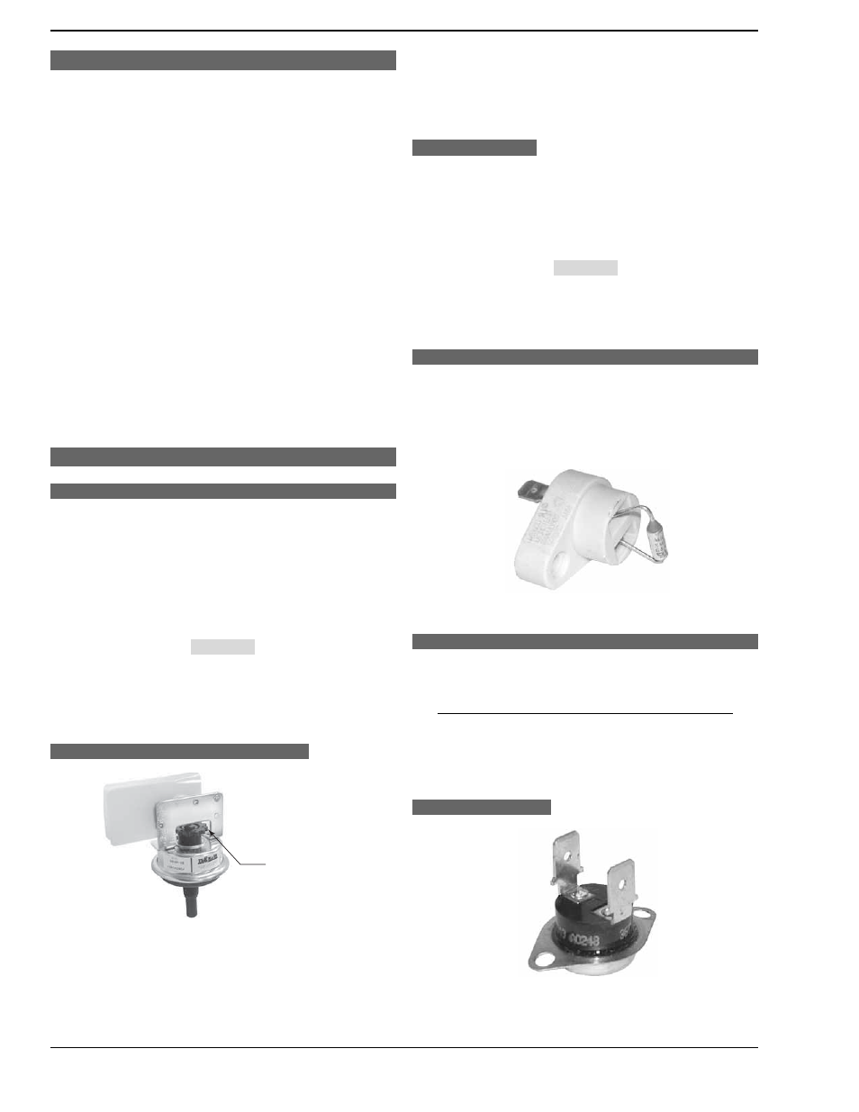
Figure 25. Flame Roll-Out Safety Switch.
H
IGH
L
IMITS
The heater is equipped with two automatic high limits.
Both are located in the In/Out header. Both are set to open at
135°F.
NOTE: An erratic high limit is often characteristic of
an internal heat exchanger problem, e.g. scale
build-up, defective bypass. Refer to Troubleshooting
section.
H
IGH
L
IMIT
R
EMOVAL
Figure 26. High Limit Switch.
1. Shut off main electrical power switch to heater.
2. Remove In/Out inspection panel.