Calibration procedure - dual port 3-4, Calibration procedure - dual port -4, Calibration procedure - dual port – Anritsu S251C User Manual
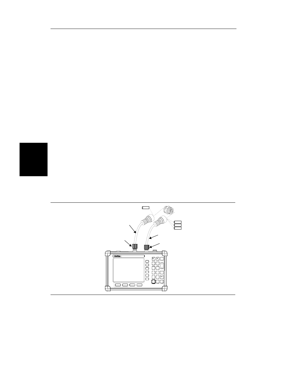
Page 41: Start cal, Enter, Figure 3-3. two-port measurement calibration setup
Calibration Procedure - Dual Port
Check that the “CAL OFF” message is displayed in the upper left corner of the display.
This indicates that the Site Master has not been calibrated. The following procedure details
how to perform the calibration. Two port calibration requires two Load components.
Step 1. Select the appropriate frequency range, as described in the procedure on page
Step 2. Press the
START CAL
key. The message
CONNECT OPEN TO RF Out
PORT will appear in the display.
Step 3. Connect the calibrated Open and press the
ENTER
key. The messages
Mea-
suring OPEN and then CONNECT SHORT TO RF Out PORT will appear.
Step 4. Remove the Open, connect the calibrated Short and press the
ENTER
key. The
messages
Measuring SHORT and then CONNECT LOAD TO RF Out
PORT will appear.
Step 5. Remove the Short, connect the calibrated Load and press the
ENTER
key. The
messages
Measuring LOAD and then CONNECT LOADS TO RF Out AND
RF In PORTS will appear.
Step 6. Connect the calibrated Loads to the RF Out and RF In ports and press the
ENTER
key. The messages
Measuring ISOLATION and then CONNECT RF
Out PORT TO RF In PORT will appear.
Step 7. Remove the Loads, connect the RF Out PORT extension cable to the RF In
PORT extension cable, using the proper adapter for the cable connector type,
and press the
ENTER
key. The message
Measuring THRU will appear.
Step 8. Verify that the calibration has been properly performed by checking that the
CAL ON message is now displayed in the upper left corner of the display.
Chapter 3 Getting Started
3-4
HOLD
RUN
START
CAL
AUTO
SCALE
SAVE
SETUP
RECALL
SETUP
LIMIT
MARKER
SAVE
DISPLAY
RECALL
DISPLAY
MODE
FREQ/DIST
AMPLITUDE
SWEEP
SYS
ENTER
CLEAR
ESCAPE
ON
OFF
/
1
2
4
5
6
7
8
9
0
3
+
-
.
Site Master S251C
LOAD
OPEN
LOAD
SHORT
RF OUT TEST PORT
RF IN TEST PORT
TEST PORT CABLE
(OPTIONAL)
TEST PORT CABLE
(OPTIONAL)
Figure 3-3.
Two-Port Measurement Calibration Setup