Dyno graph overview, Quadrant 3, Quadrant 4 quadrant 2 quadrant 1 – Penske Racing Shocks 8900 Series User Manual
Page 30
30
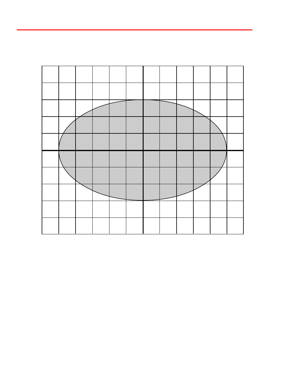
Dyno Graph Overview
-1.20
-1.00
-.80
-.60
-.40
-.20
+.0
+.20
+.40
+.60
+.80
+1.00
+1.20
Displacement (Inches)
Quadrant 3
+750
+600
+450
+300
+150
0
-150
-300
-450
-600
-750
Force (Lbs)
Quadrant 4
Quadrant 2
Quadrant 1
This section of the manual illustrates different valving combinations in the form of graphs. The graph
shown is force vs. displacement graph. The force vs. displacement graph is a very accurate and
simple way to assess valving characteristics. If you are not familiar with this type of graph, it is ex-
plained on the following page along with the graph above, showing the four different quadrants.