Manley STEREO VARIABLE MU LIMITER / COMPRESSOR - 3/2004 User Manual
Page 16
*NOTE: As of 03/2012, units are shipping with hole plugs covering the ADJUST trimmers to discourage
inadvertent un-calibrating of the triode-to-triode balance.
ADJUSTMENT PROCEDURE:
Turn the unit’s power on, and allow a minimum 45 minute warmup before attempting calibration. If new tubes have been
installed, final calibration should be done after a minimum of 8 hours burn-in time in order to stabilize the tubes.
Connect the signal source to the input of the unit, and the output metering device to the output of the unit (note that this is
balanced input/output- to utilize an unbalanced meter/ signal generator, input the signal “hot” side on XLR pin 2; pins 1 &
3 are connected together and are “ground”).
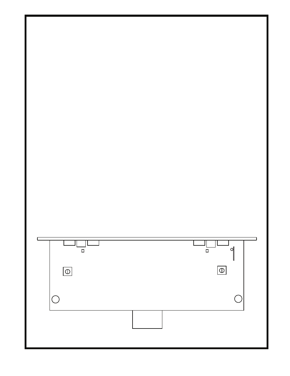
Refer to the adjustment layout drawing at the bottom of this page. Perform the adjustments in the order indicated:
1) DC BALANCE: Connect the digital multimeter to the front panel “Balance” test jacks; set the meter to read DC
VOLTS on it’s lowest scale (usually 200mv). Adjust trimpot “1” (front panel) to indicate 0V or – 10mv.
2) METER ZERO, LIMIT MODE: Adjust Meter Zero trimpot “2” so that the front panel meter reads “0”. Note that this
is a 10-turn pot; turning the pot CCW on the right channel moves the needle to the left, CW to move the needle to the left
on the left channel.
3) METER ZERO, COMPRESS MODE: Switch the “Compress/Limit” switch to “Compress”. Adjust trimpot “3” to
set the meter to “0”. Switch back to limit to confirm there is no meter movement between modes.
4) CHANNEL GAIN BALANCE (MSLC82600 and up; no gain adjust on older units): Set “Dual Input” control to
approximately 12 o’clock. Monitor the right channel output signal from the unit, and adjust the signal generator to obtain
an output level of +10 to+12dBm at the output XLR. Advance the “dual input” control beyond 12 o’clock if necessary.
Using the right channel level as a reference, now measure the output of the left channel. Adjust trimpot “4” so that the
channels match levels.
5) METER GAIN REDUCTION ACCURACY: Set to “limit” mode. Establish a reference level with the external meter
as was done in the previous step, and turn the “threshold” knob CCW to obtain an actual 6dB gain reduction at the output
of the unit. Adjust trimpot “5” so that the unit’s meter reads “6”. Now turn the “threshold” control back to full CW, and
re-zero the meter with trimpot “2”. Since trimpots “5” and “2” are interactive, this may require a few iterations to obtain
an accurate reading on the unit’s meter. Repeat this step as necessary.
6) OUTPUT STAGE BALANCE: Trimpot “6” adjusts the AC balance of the unit’s output stage; if the 7044/5687 tubes
were purchased from the factory, trimpot “6” can be set in the middle of its range as the factory-supplied tubes will have
the two triode sections matched. If the unit has old or unmatched tubes, input a music source to the unit; set to “limit”
mode, attack and recovery to fastest setting, and adjust the “threshold” control for an average of 6-8dB limiting. Listen to
a percussive track (drums, acoustic piano), and adjust trimpot “6” to minimize any “pop” heard on transient attacks.
3
5
METER CAL
3
6
5
METER CAL
1
2
2
1
6
16
4