Front panel, Diagram 2 – Manley СORE REFERENCE CHANNEL STRIP - MCORE026 and up 7/2014 User Manual
Page 5
c
o
r
e
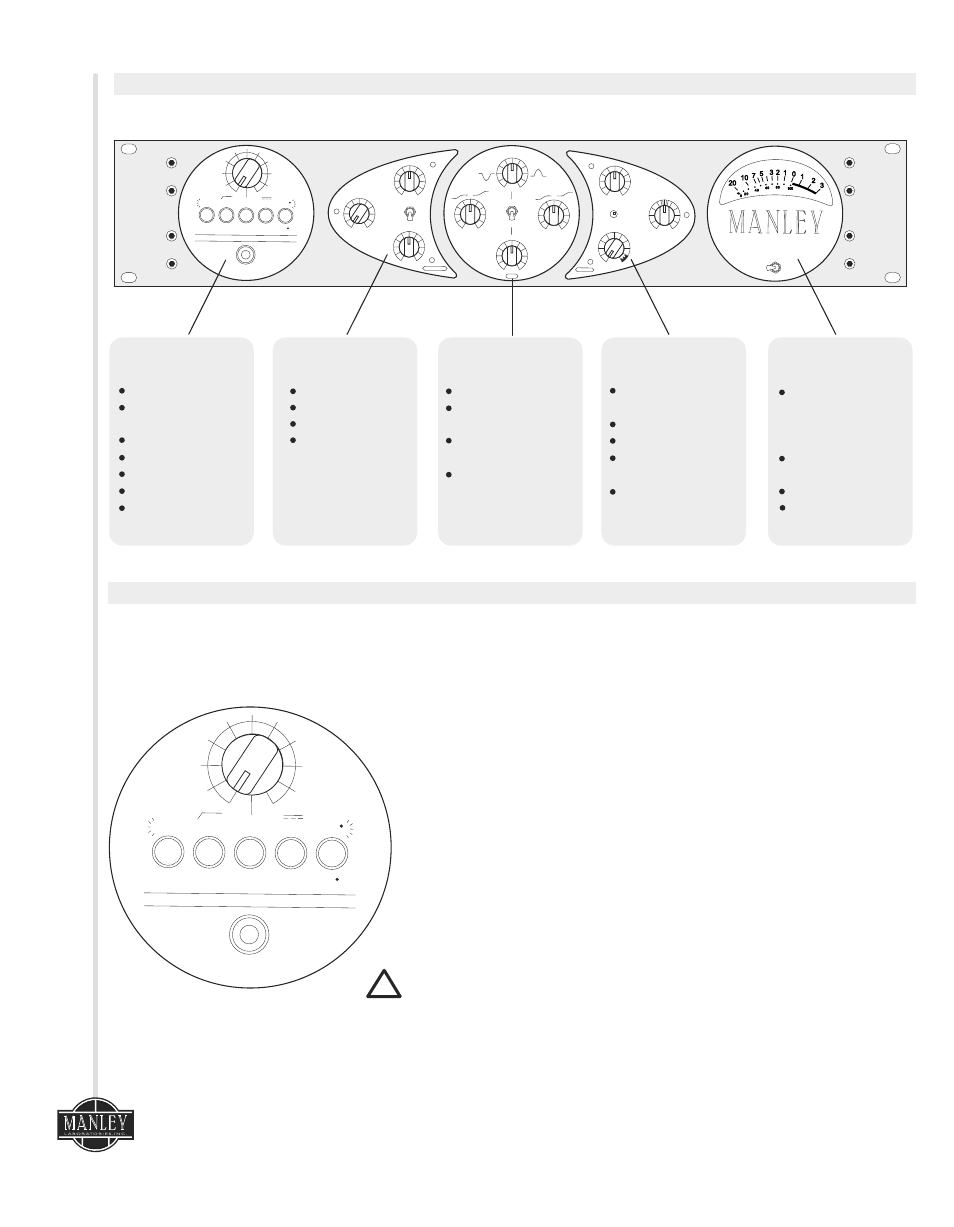
3. Front Panel
c
o
r
e
REFERENCE CHANNEL STRIP
0
O/P 1
GR
O/P 2
LOW
0
-12
+12
dB
MAX
MIN
COMPRESSION
IN
BYPASS
FAST
ATTACK
SLOW
FAST
COMPRESSOR
SLOW
RELEASE
INPUT
LEVEL
MIC
MIC
FLAT
0
180
120Hz
HI
LOW
LINE
PHANTOM
48V
HANDCRAFTED IN CALIFORNIA USA
DIRECT IN
FREQUENCY
100Hz-1kHz
1kHz-10kHz
-10
+10
dB
0
MIN
MAX
E Q
HI
-12
+12
dB
LIMITER
UNITY
LIMIT
MAX
LIMITING
RELEASE
SLOW
FAST
OUTPUT
GAIN
-6
+4
dB
MIN
PREAMPLIFIER
Input Attenuator
Mic/Line
Source Select
High Pass Filter
High/Low Gain
Mic 48V Phantom
Mic Phase Invert
Instrument
Direct Input
COMPRESSOR
Attack
Release
Bypass
Compression
(Threshold)
EQ
High & Low Shelf
Sweepable Mid
Frequency
Low/High Range
Select
Continuously
Variable Frequency
Selection
LIMITER
Limiting/Threshold
Release
Fast Attack FET
Brickwall Limiter
Limit LED
Indicator
Output Gain
Control
VU METER
Meter Source
Select Switch
Displays Audio;
Compressor
Gain Reduction
Tube Preamp Out
Final Output
As the signal flow in the CORE is from right to left, we'll describe the functions in that order as well:
4. Input Section
Diagram 2
INPUT
LEVEL
MIC
MIC
FLAT
0
180
120Hz
HI
LOW
LINE
PHANTOM
48V
HANDCRAFTED IN CALIFORNIA USA
DIRECT IN
The INPUT LEVEL control is an input attenuator. It functions like a
variable pad. It acts on the Direct In (DI), Mic and Line inputs. Fully
counter-clockwise is off, and clockwise rotation increases the level. For
the Mic input, fully clockwise represents about 40dB of gain.
With the gain switch set to LOW and the input level set fully clockwise
the MIC input will yield about 40dB of gain and the LINE input will
produce 20dB of gain.
The top label of the selector switches show operational status when the
button is pushed in and illuminated.
MIC/LINE selects either the MIC XLR input or it selects the LINE XLR or
DI 1/4 “ inputs.
The 120Hz high pass filter position is useful for reducing breath “pops,”
or any time a reduction of LOW frequencies such as train or traffic
rumble or air conditioning rumble.
The HI/LOW gain switch adds 20dB of gain to the circuit when engaged.
For most applications, this switch can be in the LOW position, but for
low output microphones or quiet sources, extra gain may be needed.
48 Volt “PHANTOM” power is applied to the Mic input XLR when this
switch is engaged. This should only be used for microphones that
require phantom power.
0
0
0 / 180 - The Mic phase switch inverts the signal by 180 degrees when
engaged.
DIRECT IN, Instrument input. This 1/4 inch input jack is for use with
guitars, keyboards, or any other instrument. When a plug is inserted
the CORE will automatically switch to the DI input. The Mic/Line switch
must be set to the Line position to activate the DI. This is an
unbalanced 10 MegOhm input that will not load down Hi Z instruments
such as a guitar. The connections on this TS Jack are TIP-HOT, SLEEVE-
GROUND.
!
4