Tube channel, Cool channel – Manley TNT MICROPHONE PREAMPLIFIER User Manual
Page 5
TNT
+22
+10
0L
SIG
OUTPUT
INPUT
POWER
ON
OFF
60s
70s
CLEAN
IRON
TRIM
GAIN
INSTRUMENT
FILTER
60 Hz
120 Hz
FLAT
PHANTOM
PHASE
ON
OFF
180
0
TRIM
GAIN
INSTRUMENT
3MEG
1MEG
300K
10K
2400
600
FILTER
80 Hz
FLAT
PHANTOM
PHASE
ON
OFF
180
0
IMPEDANCE
Ω
20
25
30
35
40
45
50
55
60
65
70
20
25
30
35
40
45
50
55
60
65
70
2
3
0
-1
300c
300
600
2K
2M
10M
100K
300K
1M
3M
BY MANLEY LABS
IMPEDANCE
Ω
TUBE
CHANNEL
COOL
CHANNEL
+6
+10
-10
-4
0
-8
-6
-2
+8
+4
+2
P
B
+6
+10
-10
-4
0
-8
-6
-2
+8
+4
+2
P
B
COLOR
P
B
P
B
1 3
8 10
15
2 4 5 6 7 9 11 12 13 14 16 17 18
5
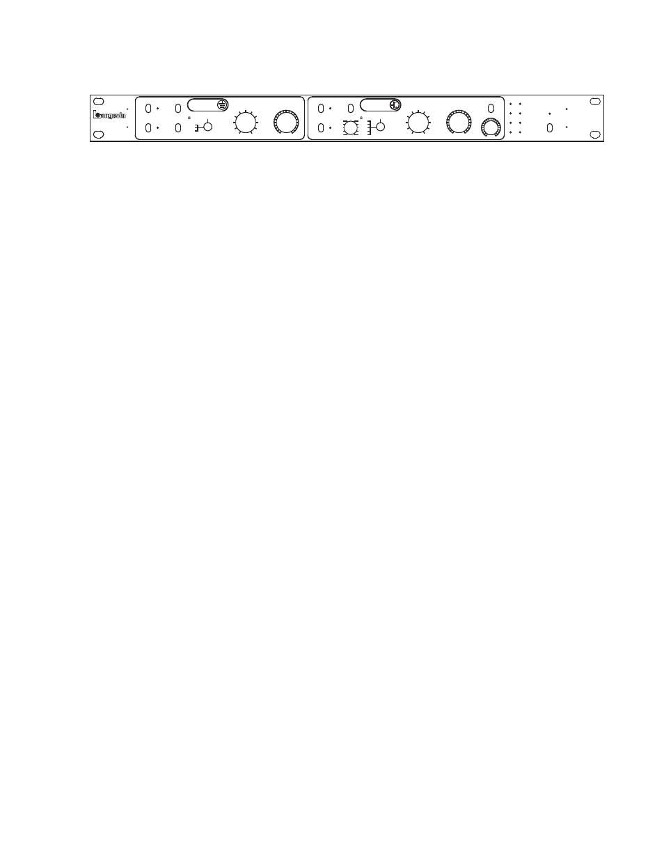
THE FRONT PANEL
TUBE CHANNEL
1) PHANTOM POWER: Toggle up turns 48 volt phantom power on (and the red LED) which is needed for most FET condenser
microphones. Turn your monitors down because it may make a big ‘POP’. Avoid patching the mic lines if phantom is turned on. Some
ribbon mics can be damaged if phantom is on and cables or patches are changed, so don’t use phantom with ribbons - or be careful.
2) PHASE SWITCH: Reverses the polarity (180 degrees) of the microphone signal. Sometimes needed in situations where two mics
are used and sometimes useful for vocals when headphones are used. Amber LED is ON when PHASE switch is engaged.
3) HIGH PASS FILTER: Toggle up engages a basic 80 Hz filter. Used to remove excess lows, rumble and some air conditioning
noise.
4) IMPEDANCE SWITCH: 3 position toggle changes the loading characteristics presented to the microphone or instrument. This
can subtly change the sound of the mic. “2400” ohms is considered normal or typical. “10K” is a lighter load and may be appropriate
for some sounds and often for ribbon mics. “600” ohms may tighten up the lows on some mics. Unlike many Impedance switches, the
volume will not change by 6 dB, and will stay relatively constant making comparisons easier. The numbers to the right of the switch
indicate the impedance given on the 1/4” Instrument Input, where 1 Meg simulates a typical amp. Higher usually means brighter.
5) INSTRUMENT INPUT: Plug your guitar or bass in here. A plug inserted in this jack will disable the XLR Microphone Input.
6) GAIN SWITCH: This rotary switch sets the gain for the first amplification stage. The steps range from +20 dB to +70 dB and
when used with the TRIM (below) provides a range of +10 to +80 dB of gain. The bottom two LEDs (see #17) indicate “signal pre-
sent” and “overload” of this first stage. If internal jumpers are properly set, one can turn this switch higher for overdrive and turn down
the GAIN TRIM to optimise the level again. If the jumpers are set for “clean” then it may be difficult to overdrive this stage.
7) GAIN TRIM POT: This pot is typically used to finely adjust the gain as needed for the recording device or converter. The two top
LEDs are associated with this knob, and are intended to help set optimal levels, which are well (about 10dB) below when the TNT
clips.
COOL CHANNEL
8) PHANTOM POWER: Toggle up turns 48 volt phantom power on (and the red LED) which is needed for most FET condenser
microphones. Turn your monitors down because it may make a big ‘POP’. Avoid patching the mic lines if phantom is turned on. Some
ribbon mics can be damaged if phantom is on and cables or patches are changed, so don’t use phantom with ribbons - or be careful.
9) PHASE SWITCH: Reverses the polarity (180 degrees) of the output signal.
10) HIGH PASS FILTER: Toggle middle position is a 120 Hz HP filter, Toggle up engages a less drastic 60 Hz filter.
11) IMPEDANCE SWITCH: This is a 5 position rotary switch that both controls the loading on a connected microphone and in-
ternally directs and shares the signal between two different preamp circuits or topologies. The least amount of loading is the 2 MEG
setting and the next setting marked 2K (2000 ohms) might be considered traditional or typical (most preamps were designed for 2000
to 3000 ohms). Both of these two only use the cascode FET preamp. The next two settings share both the cascode FET preamp and the
current mode preamp, 600 and 300. The final setting, 300C, only uses the current mode preamp and relays bypass the sub-circuit used
for mixing the preamps, so it has some purist function.
12) INSTRUMENT INPUT: Plug your guitar or bass in here. A plug inserted in this jack will disable the XLR Microphone Input.
13) GAIN SWITCH: This rotary switch sets the gain for the first amplification stage. The steps range from +20 dB to +70 dB and
when used with the TRIM (below) provides a range of +10 to +80 dB of gain. The bottom two LEDs (see #17) indicate “signal pre-
sent” and “overload” of this first stage. Use this switch in conjunction with the 60’s-70’s switch and the LEDs to control the amount of
color or distortion. In this situation the GAIN SWITCH becomes a “drive” control too.
14) GAIN TRIM POT: This pot is typically used to finely adjust the gain as needed for the recording device or converter. The two
top LEDs are associated with this knob, and are intended to help set optimal levels, which are well (about 10dB) below when the TNT
clips.
15) COLOR SWITCH: With the switch in 60’s or 70’s, a circuit is added that is designed to clip in an interesting way that somewhat
simulates the way magnetic tape, and guitar amps clip. Use the GAIN SWITCH to control the depth of distortion. In general best
results are obtained when the desired effect is subtle and this circuit is just lightly driven and obvious distortion is minimal. Of course,
sometimes more drastic effects are desired and the GAIN SWITCH can be turned up. Thicker distortion may take several processors.
The 60’s - 70’s switch can alter the highs depending on drive levels.
16) IRON EFFECT: This knob adjusts how audible the output transformer may be from exaggerated at +3 to near zero at 0 and even
becoming inverse or the opposite of a transformer at -1. This control is essentially “out-of-circuit” with the knob straight up (12:00)
(like an EQ). The knob controls several subtle effects including low frequency level, low frequency distortion, high frequency level
and high frequency dynamics. This control is often subtle and somewhat signal dependent.
17) LED LEVEL INDICATORS: Simple indicators to show signal presence, first stage clipping, and more or less appropriate levels
for the next device. See page 000 for more details.
18) POWER SWITCH: With this switch UP, LEDs should come on and maybe sounds might come out the back XLRs......