Demon Fuel Systems 190004 User Manual
Page 2
2
accelerator pump override spring by tightening the nut until some clearance is visible between the
bolt head and pump lever. Back the nut off until all clearance is removed and then rotate it another
1/8 turn. Setting the initial float level may be done easily by inverting the fuel bowl (before it is
installed). Run the new fuel inlet (needle & seat) assembly in until the top of the float is parallel with
the roof of the fuel bowl.
Once a Demon™ or BG Claw carburetor is in place and the engine is running, the level should be set
such that it is in the middle of the sight window. Again, adjust the idle mixture screws to provide the
highest manifold vacuum or engine RPM.
Once a HOLLEY® carburetor is in place and the engine is running, the level should be set so that fuel
is just below the inspection hole and the mixture screws should be adjusted to provide the highest
manifold vacuum reading or engine RPM.
1. Remove the primary fuel bowl. Four screws, located at each corner of the bowl (Fig. 1), hold both
it and the metering block in place. When either one of the lower screws is loosened, fuel will begin
seeping out, unless the carb has been drained. If the carburetor has been in service for some
time, the screw gasket will tend to stick to the fuel bowl.
Figure 1
2. Once all four screws are removed, the bowl can be pulled away from the metering block.
Depending upon the age of the carburetor, this may not be quite as easy as it seems. Some
carburetors are assembled with composition gaskets and some were coated with a sealing resin
to eliminate fuel vapor seepage. A gentle pry with a wide blade screwdriver should solve the
problem. The same technique must also be applied to the metering block in order to separate it
from the main body. When the fuel bowl is pulled from a carburetor with a single fuel inlet, the "O"-
ring that seals the fuel transfer tube will generally remain inside the housing. It should be pulled
out and discarded at this point, so that it doesn't become mixed with the new rings. The inlet fitting
may be removed with an 11/16
” wrench.
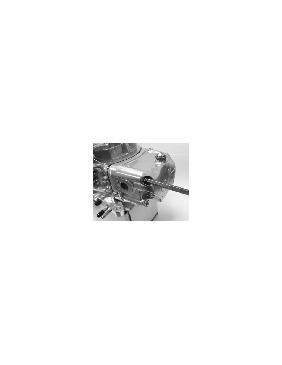
3. After removing the lock screw, the fuel valve & seat assembly may be rotated counter-clockwise
with a 5/8-inch wrench. Once the threads are no longer engaged with the bowl threads, the entire
assembly can be extracted (Fig. 2). O-rings may provide some resistance which can be easily
overcome by pulling straight upward.