Preventing test port connector damage, Safety recommendations – Boonton Average & CW Power Sensors User Manual
Page 4
Wireless Telecom Group Inc.
25 Eastmans Rd
Parsippany, NJ 07054
United States
Tel:
+1 973 386 9696
Fax:
+1 973 386 9191
www.boonton.com
© Copyright 2012
All rights reserved.
B/SensConnCare/0212/EN
Note: Specifications, terms and conditions
are subject to change without prior notice.
Preventing Test Port Connector Damage
• Keep connectors clean and protect using the plastic end
caps provided with each sensor.
• Inspect connectors regularly, and look for metal debris,
scratches or dents.
• Clean contact surface and threads with clean & dry com-
pressed air.
• Align connectors first and only rotate the connector nut.
• Always follow MIL-C-39012 standards for making a con-
nection
• A MIL-C-39012 or precision type “N” connector is recom-
mended for the RF line signal source connection
• After proper alignment, rotate the connector nut by hand
to connect, or disconnect the connector of the sensor from
a signal source or power meter.
• If “N” connector is not equipped with a hex, it is recom-
mended to use a specified mating torque.
• Do not over-tighten the connector by using the sensor
body for additional leverage
1) Only rotate the connector nut, DO NOT use the sensor body
or device to tighten the connector.
2) Do not use a torque wrench to tighten the connector.
3) Do not use a connector with deformed threads, or a bent or
broken conductor.
4) Do not touch mating-plane surfaces with oily, or wax-like
non-conductive substances
5) Do not apply a lateral force to the center conductor
Safety Recommendations
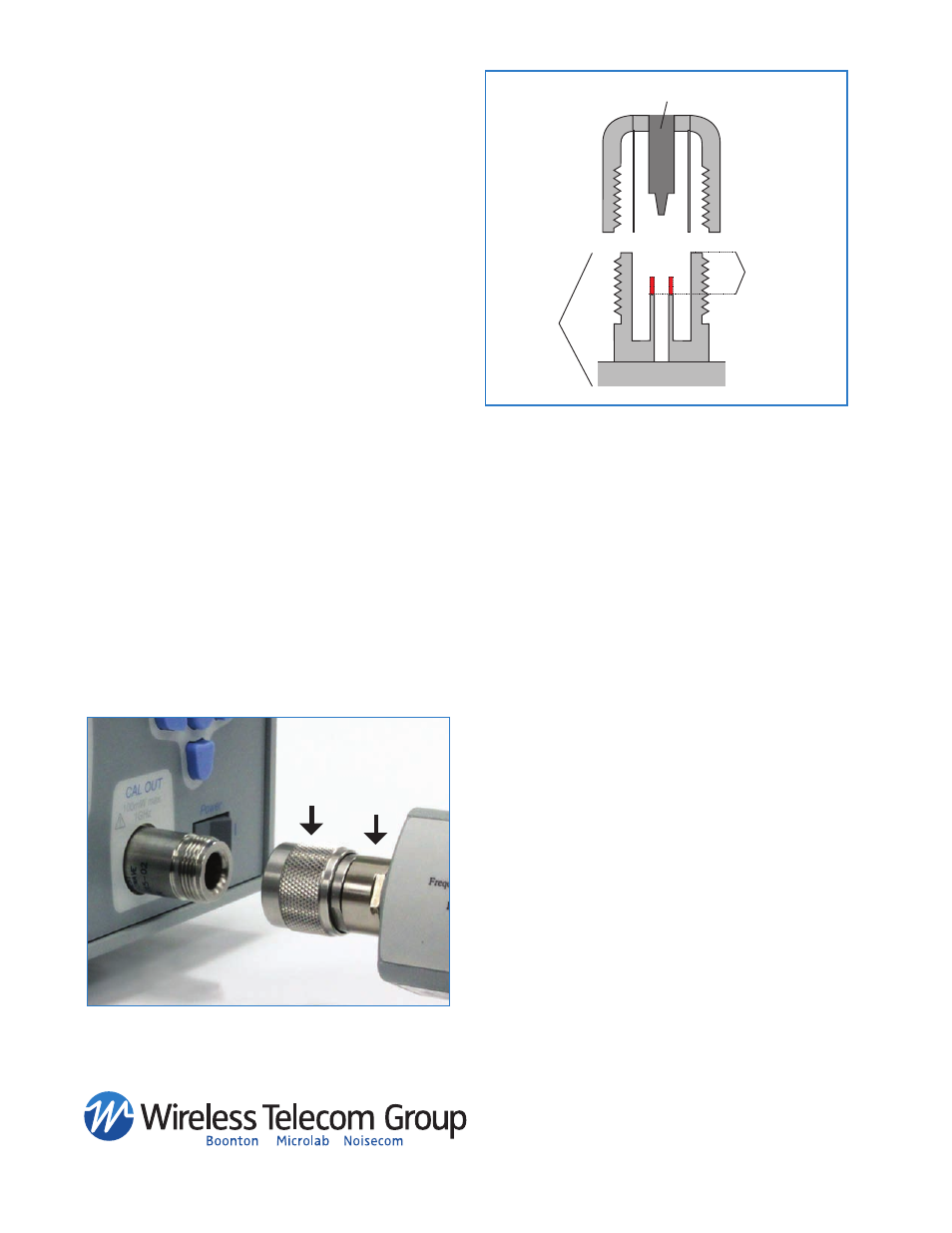
Figure 12.
TIGHTEN
HOLD
Type-N (m)
Type-N(f)
Required Depth
Conductor Pin
Bulkhead
NOTE: A common cause for “N” Type Connector damage is a bulk-
head without the required mating connector depth (Red Projection).