Boonton power sensor connectors – Boonton Average & CW Power Sensors User Manual
Page 2
2
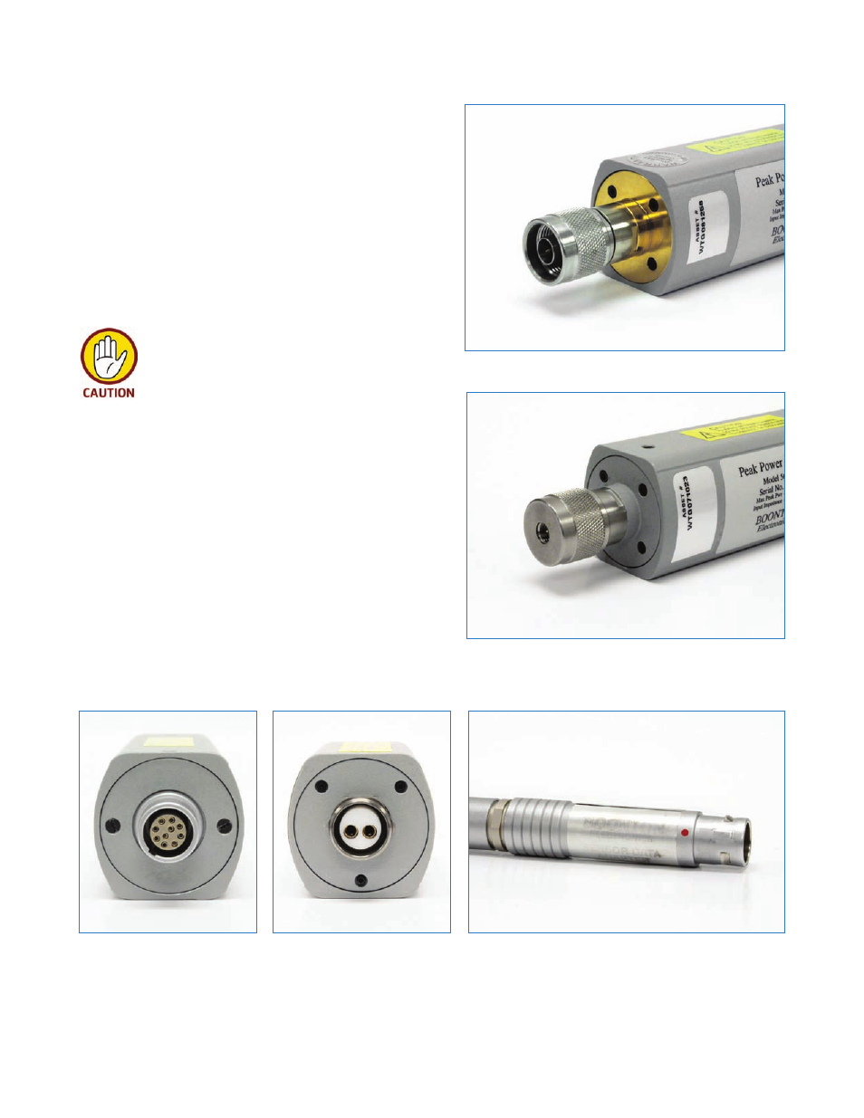
Figure 3. Peak sensor with ten-pin
connector for signal and communica-
tions
Boonton Power Sensor Connectors
Boonton peak and average power sensors have either an “N”
or “K” type RF signal connector depending on the sensor fre-
quency range shown in Figures 1 and 2. Newer sensor models
have a ten-pin connector for signal and data communication
connection to the power meter base module.(see Figure 3)
Average power sensors have a two-pin signal connector for
use with existing Boonton meters, but can be purchased or
matched with a ten-pin data adapter that allows connection
to newer power meter models. (See Figure 5).
When selecting a sensor, be sure of the maxi-
mum peak and average RF input power value.
RF signal inputs above the sensor‘s specified
upper power limit may result in permanent
damage to the detector circuitry.
Figure 4. Average sensor with two-
pin connector
Figure 5. Data adapter for average sensor models
Figure 1. Sensor with N(m) RF connector
Figure 2. Sensor with K(m) RF connector