Sensor connection & recommendations – Boonton Average & CW Power Sensors User Manual
Page 3
3
Sensor Connection & Recommendations
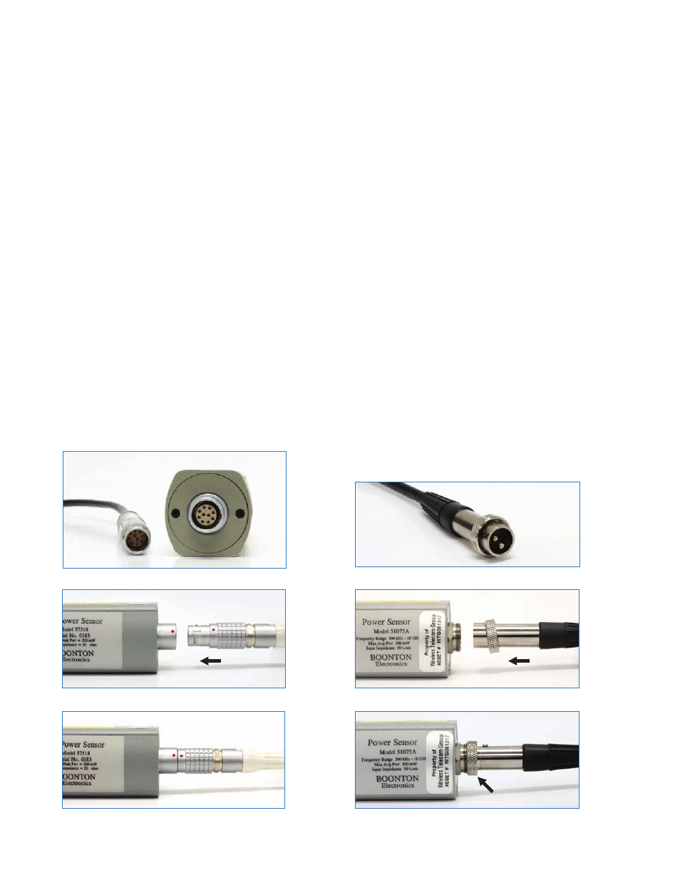
Ten-Pin Connection
1) Connect the peak sensor’s ten-pin connector to the sensor
cable by aligning the red mark on the cable connection
with the mark on the sensor connector and pressing the
connectors together until they engage. (See Figure 7)
2) Connect the other end of peak sensor cable to the Channel
1 or 2 input in a similar manner.
3) The instrument will download the factory installed cali-
bration data from the sensor memory while the sensor is
connected to the power meter and display “Sensor Data
Loading”.
4) Do not hold the sensor body while taking measurements.
This can result in measurement error due to temperature
increase.
5) Before making measurements with Boonton power me-
ters, the sensor should be connected to the instrument’s
built-in calibrator and calibrated. This applies for units
with an on-board or optional external calibrator. The cali-
bration is required for peak sensors.
Two-Pin Connection to Data Adapter
1) Connect the sensor to the cable by pressing both two-
pin connectors together being careful to align the pins
and ONLY hand-tighten the connector nut without cross
threading.
2) Intruments with ten-pin input connectors will down-
load the factory installed calibration data from the sen-
sor adaptor memory while the sensor is connected to the
power meter and display “Sensor Data Loading.”
3) If the sensor is disconnected during the download process
or an error message appears on the power meter display,
disconnect and reconnect the sensor and press the “CLR”
button.
4) Do not hold the sensor body while taking measurements.
This can result in measurement error due to temperature
increase.
5) Before making measurements with Boonton power me-
ters, the sensor must be connected to the instrument’s
built-in-calibrator and calibrated. This applies for units
with an on-board or optional external calibrator. The cali-
bration is required for peak sensors.
Figure 9. Two-pin connector
Figure 8. Peak sensor connector and the sensor cable (closed)
Figure 6. Circular ten-pin connector
Figure 10. Average sensor connector and sensor cable (open)
Figure 7. Peak sensor connector and the sensor cable (open)
Figure 11. Average sensor connector and sensor cable (closed)
PUSH
“CLICK!”
TIGHTEN
PUSH