4 internal components – Asus Vintage-AH1 User Manual
Page 17
1 - 7
1 - 7
1 - 7
1 - 7
1 - 7
A S U S V i n t a g e - A H 1
A S U S V i n t a g e - A H 1
A S U S V i n t a g e - A H 1
A S U S V i n t a g e - A H 1
A S U S V i n t a g e - A H 1
1.
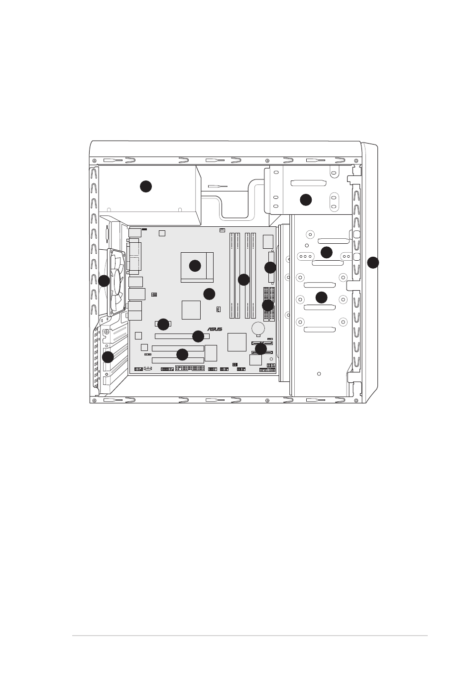
Power supply unit
2.
5.25-inch drive bay
3.
Floppy disk drive bay
4.
ATX power supply connector
5.
Socket 939 for AMD Athlon™
64/AMD Athlon™ 64FX CPUs
6.
Chassis fan
7.
DIMM sockets
8.
Hard disk drive bays
1.4
Internal components
The illustration below is the internal view of the system when you remove
the top cover and the power supply unit. The installed components are
labeled for your reference. Proceed to Chapter 2 for instructions on
installing additional system components.
9.
Front panel cover
10. PCI Express x1 slot
11. ASUS motherboard
12. PCI Express x16 slot
13. IDE connectors
14. Expansion card slots
15. PCI slots
16. Serial ATA connectors
®
CR2032 3V
Lithium Cell
CMOS Power
CD
FP_AUDIO
ALC880
ATX12V
SPDIF_OUT
KBPWR
CPU_FAN
SATA1
USB78
USBPW12
USBPW34
VIA
VT6307
CLRTC
ATI
RS482
PS/2KBMS
T: Mouse
B: Keyboard
Below:Mic In
Center:Line Out
Top:Line In
F_USB12
LAN_USB34
COM2
P
ARALLEL
POR
T
VGA
Below:
Center/Subwoofer
Center:
Side Speaker Out
Top:Rear Speaker Out
IE1394_1
SATA3
SATA2
SATA4
CHA_FAN
PCIEX1_1
88E8053
Super
I/O
PCI1
GAME
FLOPPY
PCI2
PCIEX16
PANEL
4M
BIOS
FWH
SB_PWR
F_PANEL
ULIM1573
USBPW78
USBPW56
USB56
A
TXPWR
PRI_IDE
SEC_IDE
DDR DIMM_A1 (64 bit,184-pin module)
DDR DIMM_A2 (64 bit,184-pin module)
DDR DIMM_B1 (64 bit,184-pin module)
DDR DIMM_B2 (64 bit,184-pin module)
Socket 939
1
1
1
1
1
2
2
2
2
2
3
3
3
3
3
6
6
6
6
6
9
9
9
9
9
5
5
5
5
5
7
7
7
7
7
1 1
1 1
1 1
1 1
1 1
1
1
1
1
14
4
4
4
4
1
1
1
1
15
5
5
5
5
1 2
1 2
1 2
1 2
1 2
1
1
1
1
16
6
6
6
6
1
1
1
1
13
3
3
3
3
1 0
1 0
1 0
1 0
1 0
4
4
4
4
4
8
8
8
8
8