Zbd1850nii ge monogram, 18" dishwasher, For reference only – not to scale – GE ZBD1850NII User Manual
Page 3: Product specification created 3/14
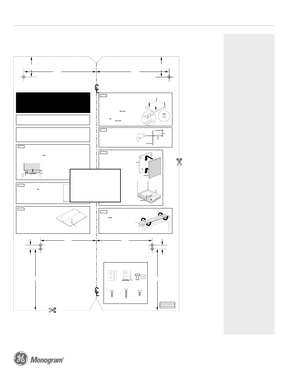
The custom door panel
and custom handle of your
choice should be secured
to the dishwasher before
installation begins. A
template with instructions
and installation hardware
is provided.
For planning purposes, you
may order the template in
advance by calling
1.800.GE.CARES
(1.800.423.2737) or by
visiting our website at
GEAppliances.com in
the United States.
In Canada, call
1.800.561.3344
or visit
www.GEAppliances.ca.
Order Pub. No.
31-30244. Complete panel
installation instructions
are included on the
template.
Maximum panel weight is
8 LBS (3.6 kg).
SPECIAL NOTES
CUSTOM DISHWASHER DOOR PANEL TEMPLATE
GE PUB. NO. 31-30244
CALL 1-800-626-2000
For a full-size panel template with complete panel installation instructions.
Product Specification Created 3/14
ZBD1850NII
GE Monogram
®
18" Dishwasher
Top of Panel
7-11/16"
Trim Around
Dotted Line
2-5/32"
(5.5 cm)
(19.5 cm)
Trim Around Dotted Line
Drill 3/32"
Pilot Hole
3/32" Deep
Top of Panel
7-11/16"
2-5/32"
(5.5 cm)
(19.5 cm)
Drill 3/32"
Pilot Hole
3/32" Deep
Drill 3/32"
Pilot Hole
3/32" Deep
13/32"
(1 cm)
6-1/2"
(16.5 cm)
5-29/32"
(15 cm)
Drill 3/32"
Pilot Hole
3/32" Deep
13/32"
(1 cm)
6-1/2"
(16.5 cm)
5-29/32"
(15 cm)
3/4" Thick Custom Panel
Template Instructions for 18"
Top Control Integrated Profile and
Monogram Dishwasher Models
Pub. No. 31-30244
Dwg. No. 206C1559P182
05-08 JR
The custom panel should be sized to your installation situation. See Step 1. For easier
installation, the custom panel and custom handle should be attached before installing the
dishwasher. Use this template to locate mounting screws and spacers on the custom panel.
IMPORTANT
• A custom handle must be installed onto the custom
panel. Install the custom handle 4-1/2" max. from
the top of the panel.
STEP 2 DRAW CENTERLINE
•
Place
the custom panel on a
surface with the
appearance side down.
•
Locate
the vertical center of the panel at the top.
•
Use
a carpenter's square to draw a centerline from
top to bottom.
STEP 3 ALIGN TEMPLATE TO PANEL
•
Trim
template on the dotted line along all sides.
•
Place
the template on the panel aligned with the top
edge and the centerline. Use tape to hold in place.
IMPORTANT: If the template is not aligned with the top
edge of the panel, the 1/2" minimum gap will not be maintained.
This 1/2" minimum gap must be maintained to prevent condensation
and damage to the control panel from screw heads.
•
Use
an awl to mark the screw hole locations indicated
on the template. Remove the template.
HEIGHT
Panel height should be 26-25/32" (68 cm).
• The top of the custom panel must be
with the top of the door. The 1/2" minimum gap
between the top of the door and the bottom of
the countertop must be maintained.
PARTS INCLUDED:
(2) Brackets
(4) 1/2" Phillips flat-head screws
(2) Spacer pads
(2) Metal spacers
(2) 1" Phillips flat-head screws
(2) 3/4" Phillips round-head screws
STEP 1 CUSTOM PANEL SIZE REQUIREMENTS
IMPORTANT: To ensure optimum door balance
performance, the custom panel must not weigh
more than 8 lbs.
WIDTH
Panel width must be 17-1/2" (44.4 cm).
• If the panel width is less than 17-1/2", it will
not cover the dishwasher frame.
STEP 7 CHECK DOOR BALANCE
To check the door balance, hold the top of the
dishwasher
•
Check
the door balance by opening and closing
the door.
•
If
the door drops when released, increase the
spring tension. If the door rises when released,
decrease the spring tension.
•
Using
a T25 torque driver, adjust in the direction
shown. Adjust both sides equally.
STEP 6 INSTALL ASSEMBLED PANEL
•
Secure
the panel to the door by inserting
the top metal spacers and bottom brackets
into the matching slots on the dishwasher
door and control panel.
•
Make
sure both metal spacers and both
brackets engage the slots.
•
Press
the panel against the door and push
downward until the metal spacers and brackets
are fully engaged into the slots. The panel should
align evenly with the top and sides.
•
Stand
the dishwasher upright.
•
Open
the dishwasher door and remove the
2 plug buttons, one on each side as shown.
•
Place
the supplied 3/4" Phillips round-head
screws inside the plastic sleeve and drive
through the inner door and into the custom
panel.
•
Replace
the 2 plug buttons by pressing them
back into the plastic sleeve.
WARNING: Do not overtighten screws. Excessive
tightening of the screws could damage door edges.
STEP 5 INSTALL CUSTOM HANDLE
A custom handle must be installed onto the panel
before the panel is secured to the dishwasher door.
•
The
handle should be installed so that it aligns with
adjacent drawer handles,
or 4-1/2" max. from the
top of the panel. Secure the handle in the same
manner as the cabinet handles. Screws must be
countersunk into the panel.
STEP 4 INSTALL MOUNTING SCREWS AND SPACERS
Note: The custom panel is secured to the dishwasher door
with the metal spacers, screws and brackets provided.
The metal spacers and brackets will slip into the slots
on the dishwasher door and control panel.
•
Align
the metal spacers over the top pilot holes. Ensure
the thick, recessed side is facing up.
•
Drive
the supplied 1" Phillips
screws through
the metal spacers and into the panel.
•
Align
the brackets over the bottom pilot holes. Ensure
the curved
lip is facing up. If the back surface of the
panel is not
use the spacer pads provided.
•
Drive
the 1/2" Phillips
screws through the
brackets and into the panel.
Countertop
Minimum 1/2" gap
for clearance
1/2" minimum
Mark center
screw holes
Bracket
Spacer Pad
Spacer
Handle
4 1/2" Max.
from top
of panel
Custom
door panel
Screws must be counter
-
sunk into panel
Custom
panel
Dishwash-
er door
Custom panel
PARTS SUPPLIED
(2) Brackets
(2) Spacer Pads
(2) Metal spacers
(2) 3/4" Round-head
screws
(4) Phillips flat-head
screws
(2) Phillips flat-head
screws
Increase
Decrease
Decrease
Increase
Instructions de gabarit pour panneau
sur mesure épais de 19 mm (3/4 po)
pour modèle de lave-vaisselle à réglage
intégré en haut Profile et Monogram
Le panneau de finition doit avoir des dimensions appropriées pour l’installation. Consulter l’étape 1.
Pour faciliter l’installation, le panneau de finition et la poignée de finition doivent être montés avant la mise
en place du lave-vaisselle. Utiliser ce gabarit pour déterminer l’emplacement des vis de montage et
des rondelles sur le panneau de finition.
IMPORTANT
le panneau de finition. Installer la poignée à
moins de 11,5 cm (4-1/2 po) du haut du pan
-
neau.
ÉTAPE 2 TRAÇAGE DE L’AXE
• Mettre le panneau de
sur une surface plate, le côté extérieur
vers le bas.
• Mettre le centre vertical du panneau en haut.
• Avec une équerre de menuisier, tracer un axe du haut au bas.
ÉTAPE 4 INSTALLER LES VIS DE MONTAGE ET LES RONDELLES
ÉTAPE 5 INSTALLATION DE LA POIGNÉE DE FINITION
• Mettre le lave-vaisselle debout.
• Ouvrir la porte du lave-vaisselle et visser les vis à tête bombée
fournies nº 8 x 1-3/4 po. Visser une vis en haut et une en bas, à
travers le panneau interne de la porte et le panneau de
ATTENTION : Il ne faut pas serrer les vis en excès. Un serrage
excessif des vis peut endommager les bords de la porte.
• Couper le gabarit suivant le pointillé, sur tous les côtés.
• Mettre le gabarit sur le panneau, aligné sur le bord supérieur et sur l’axe.
Le maintenir en place avec du ruban adhésif.
IMPORTANT : Si le gabarit n’est pas aligné à l’extrémité du haut du panneau,
vous n’obtenez pas 1/2 po d’espace libre. Vous devez avoir un espace libre de
1/2 po pour empêcher la condensation et éviter d’endommager le panneau de
contrôle avec les têtes de vis.
• Avec un pointeau, marquer les emplacements de trous de vis indiqués
sur le gabarit. Enlever le gabarit.
HAUTEUR
Le panneau doit avoir entre au moins 30 1/16 po et 30 1/4 po
de hauteur.
•
Si
le panneau a plus de 30 1/4 po de hauteur, il empêche la
porte de s’ouvrir complètement.
•
Si
le panneau a moins de 30 1/16 po de hauteur, il ne couvre
pas le châssis de porte du lave-vaisselle.
Numéro de publication 31-30569-1
Nº de plan 206C1559P109
07-04 JR
PIÈCES INCLUSES :
(4) Rondelles
(4) Vis nº 8 x 5/8 po à tête bombée Phillips, en acier inoxydable
(3) Vis à bois nº 8 x 1-3/4 po à tête bombée Phillips, en acier
inoxydable
(2) Ressorts pour service sévère
ÉTAPE 1 TAILLE NÉCESSAIRE
POUR LE PANNEAU SUR MESURE
Si l’épaisseur du panneau est inférieure à 19 mm (3/4 po), il faut utiliser des vis
plus courtes. Utiliser des vis nº 8 x 1/2 po (pas fournies) pour les panneaux de
13 mm (1/2 po).
• Utiliser une mèche de 2,4 mm (3/32 po) pour percer des trous guides à une
profondeur de 2,4 mm (3/32 po) aux emplacements marqués.
Remarque : Le panneau de
est maintenu en place sur la porte du lave-
vaisselle avec des rondelles et des vis fournies. La rondelle glisse dans les
trous allongés dans la porte du lave-vaisselle.
• Visser les vis nº 8 x 5/8 po à tête bombée Phillips, en acier inoxydable(four-
nies) à travers la rondelle et dans le panneau.
• Installer les rondelles et les vis restantes, comme indiqué, aux endroits mar-
qués.
IMPORTANT : Pour que la porte fonctionne
bien, le panneau sur mesure ne doit pas
peser plus de 6,4 kilos (14 livres).
CONSEIL – Si la porte ne s’ouvre pas facilement ou si elle
tombe trop rapidement,
le passage du câble des
ressorts. Le câble est maintenu en place par des
« épaulements » sur la poulie.
que le câble n’a pas
glissé sur les épaulements de poulie.
IMPORTANT – Régler l’équilibre des deux ressorts pour
avoir la même tension des deux côtés,
d’éviter un
gauchissement excessif de la porte en service.
ÉTAPE 3 ALIGNER LE GABARIT SUR LE PANNEAU
Installer une poignée de
sur le panneau avant de monter
le panneau sur la porte du lave-vaisselle.
• Il faut aligner la poignée sur les poignées des tiroirs adjacents
ou à moins de 115 mm (4-1/2 po) du haut du panneau. Monter
la poignée de la même manière que les poignées de l’armoire.
Les vis doivent être noyées dans le panneau.
ÉTAPE 6 INSTALLATION DU PANNEAU ASSEMBLÉ
• Pour monter le panneau sur la porte, insérer les vis de montage
du haut et du bas, avec les rondelles, dans les trous allongés
correspondants.
•
que les quatre rondelles s’engagent dans les trous
allongés.
• Pousser le panneau contre la porte et l’abaisser jusqu’à ce
que les rondelles sont totalement engagées dans les trous al-
longés. Le panneau doit être aligné uniformément en haut
et sur les côtés.
ÉTAPE 7 INSTALLATION DES RESSORTS DE LA PORTE
Le lave-vaisselle est expédié de l’usine avec un jeu de ressorts
d’équilibre temporaires. Il faut utiliser les ressorts pour service
sévère fournis et les trous de réglage du câble pour équilibrer
la porte après avoir installé le panneau de finition sur le
lave-vaisselle.
• Avec le lave-vaisselle sur la palette en bois, fermer et ver-
rouiller la porte.
• Enlever et jeter les deux ressorts de la porte.
• Monter les nouveaux ressorts pour service sévère de la porte.
Engager l’extrémité avec un crochet court dans la patte de
support et celle avec le crochet long dans le câble.
• Ouvrir et fermer la porte.
• Si la porte s’ouvre quand elle est relâchée, augmenter la ten-
sion du ressort. Si la porte se ferme quand elle est relâchée,
diminuer la tension du ressort.
•
Le
haut du panneau sur mesure doit
le haut de la
porte. Il doit y avoir un espace libre d’au moins 1/2 po en-
tre le haut de la porte et le bas du revêtement de comptoir.
LARGEUR
Le panneau doit avoir au moins 23 3/4 po de largeur.
•
Si
le panneau a moins de 23 3/4 po de largeur, il ne couvre
pas le châssis de porte du lave-vaisselle.
FOR REFERENCE
ONLY
–
NOT TO SCALE