AEG 25742 GM User Manual
Page 5
16
5
Contents
For the User
For Your Safety ........................................................................3
Description of the hob ..............................................................6
Instructions for use...................................................................6
Cleaning and maintenance ......................................................8
For the Installation Technician
Technical data ........................................................................12
Instructions for the installation technician ..............................13
Electrical connection ..............................................................15
Adapting to the different types of gas.....................................16
Building into fitted kitchen units..............................................17
Guide to reading the instructions
The following symbols will help you when
reading the instructions:
Safety information
"Step by step" instructions
Suggestions and Advice
Information concerning environmental protection
This appliance complies with the following EEC Directives:
-
73/23 and 90/683 (relating to Low Voltage);
-
89/336 (relating to Electromagnetic Compatibility);
-
90/396 (relating to Gas Appliances)
-
93/68 (relating to the General Standards)
and subsequent amendments.
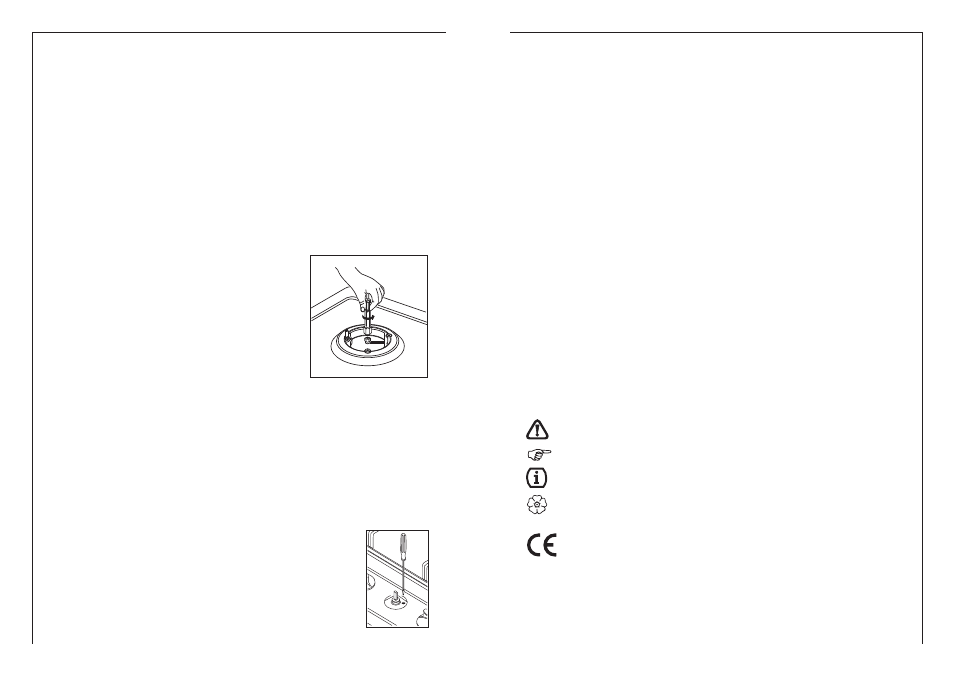
Setting the minimum level
1) Light the burner as already described.
2) Turn the tap to the minimum flame position.
3) Remove the control knobs.
4) Use a thin straight screwdriver to turn the by-pass pin located
next to the tap rod (see fig. A).If you are converting from natural
gas to LPG, turn the by-pass pin fully clockwise.
The result should be a small, homogeneous flame which is
uniform around the entire burner ring.
5) Finally, check that the burner does not go out when the tap is
turned quickly from the maximum to the minimum position.
If the lead has to be replaced, only HO5RR-F or HO5RN-F type cables suitable for
the load and the operating temperature must be used.In addition, the yellow/green
earth wire must be about 2 cm longer than the live and neutral wires.
In all cases, the power supply lead must be positioned so that it does not reach a
°
C above the room temperature in any point.
One example of an ideal route is shown in the illustration.The cable is guided by
means of band clamps fixed to the side of the cabinet, in order to avoid any contact
with the appliance underneath the hob.
Replacing the power supply lead
A
Changing the nozzles
1) Remove the pan stands
2) Remove the burner caps and flame caps from the
burners.
3) Use a size 7 socket wrench to unscrew and remove
the nozzles, replacing them with those corresponding
to the type of gas to be used (see table).
4) Reassemble the parts, reversing the operations
described above.
5) Then replace the setting data plate (close to the
mains gas connection) with the one for the new type
of gas (it is in the bag of nozzles provided).
If the pressure of the gas used is different from that specified (or variable), a suitable
piped gas pressure regulator complying with the standard must be installed on the
Adapting to the different types of gas