For your safety, Installation options, Installation – AEG 25742 GM User Manual
Page 3: During use, On base cabinet with door, On base cabinet with oven
18
3
For Your Safety
These instructions have been drawn up for your safety and that of others. You are
therefore requested to read them carefully before installing and using the appliance.
Keep this instruction manual for future reference as necessary. If the appliance is sold
or moved, make sure that the manual is handed over to the new user.
If you are unsure of any of these warnings or instructions please contact our Customer
Care Department on 08705 350350.
Installation
• Installation of the appliance and its connection to the electrical mains must only
be carried out by QUALIFIED STAFF. Before any procedure, it is important to
check that the appliance is DISCONNECTED from the electrical mains.
• Any gas installation must be carried out by a registered CORGI installer.
• It is risky to modify or attempt to modify the characteristics of this product.
• After removing the appliance from the packaging, make sure that it is undamaged
and that the electrical lead is in perfect condition. Otherwise, contact your dealer
before putting the appliance into operation.
• The Manufacturer declines all responsibility in case of failure to comply with the
manufacturer’s instructions and to the relevant British Standards.
• Make sure that air is able to circulate freely around the appliance. Poor ventilation
produces a shortage of oxygen.
• Make sure that the appliance is supplied with the type of gas indicated on the relative
sticker next to the mains gas connection pipe.
• Use of a gas cooking appliance produces heat and moisture in the room in
which it is installed. Ensure that the room is well ventilated by keeping the
air intakes open and in good working order or by installing an extractor hood
with a discharge pipe.
• If the appliance is used intensively for a long time the effectiveness of the
ventilation will have to be increased, for example by opening a window or
increasing the power of any electric extractor fan.
During use
• This hob is intended for domestic cooking only. It is not designed for commercial
or industrial purposes.
• After using the appliance, make sure that all controls are in the "OFF" position.
• When using other electrical appliances, ensure the cable does not come into contact
with the hot surfaces of the cooking appliance.
• Unstable or misshapen pans should not be used on the hob as unstable pans can
cause an accident by tipping or spillage.
• Never leave the hob unattended when cooking with oil and fats.
• Never use plastic or aluminium foil dishes on the hob.
• Perishable food, plastic items and aerosol may be affected by heat and should not
be stored above or below the hob unit.
• Do not use this hob if it is in contact with water. Do not operate the hob with wet
hands.
a
Removable panel
b) Space for connections
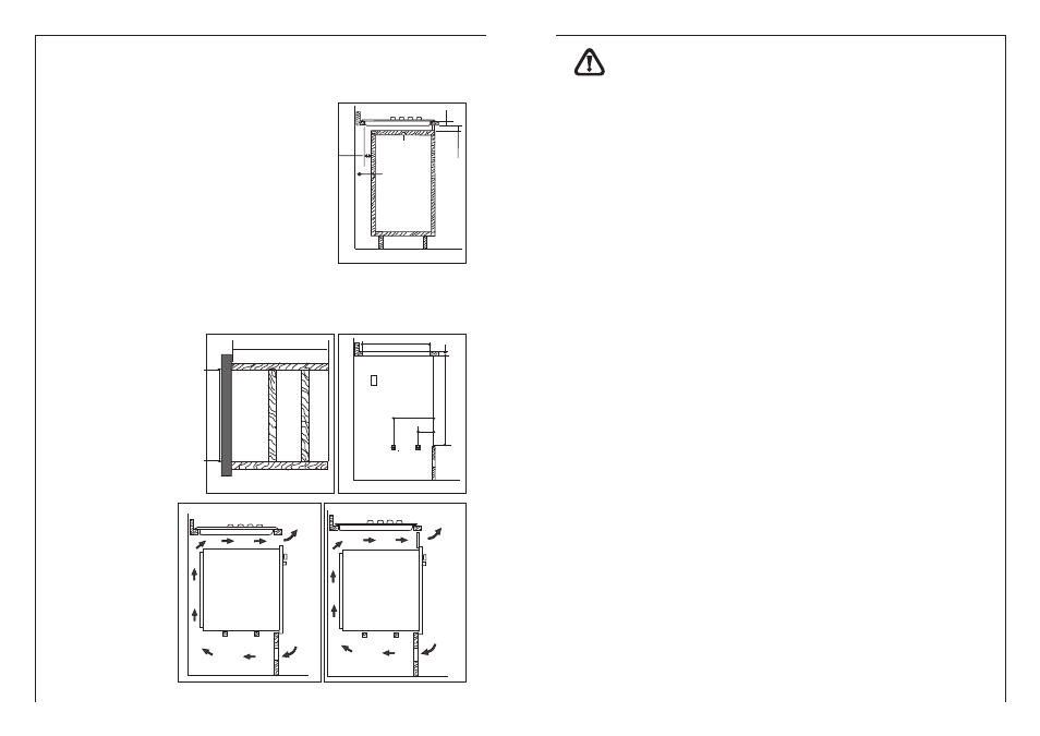
Installation options
On base cabinet with door
When constructing the cabinet, suitable precautions must
be taken to prevent contact with the casing of the hob,
which becomes very hot during operation.The
recommended method for overcoming this problem is
illustrated in fig. 1.
The panel underneath the hob must be easily removable
to allow the hob to be locked in position and released in
case of servicing work.
On base cabinet with oven
The installation compart-
ment must have the di-
mensions shown in figu-
res 2 and 3 and must
have supports to allow
satisfactory ventila-
t i o n . Tw o p o s s i b l e
methods for avoiding
overheating are illustra-
ted in figures 3 and 4.
The electrical connec-
tions of the hob and
oven must be made se-
parately both for electri-
cal reasons and to sim-
plify removal of the oven
through the front of the
cabinet.
Wall cabinets or ex-
tractor hoods must be at
least 650 mm above the
hob, subject to the ma-
nufacturer’s instructions.
60
b
a
30
20
min
Fig. 1
Fig. 2
560 min
550 min
Fig. 3
480
591
380
140
30
Fig. 4
120cm
180 cm
2
2
Fig. 3
50 cm
360 cm
2
2