Instructions, Wiring instructions, Troubleshooting – LUMATEQ LB40 Low Voltage User Manual
Page 2: Tools required, Accessories
LUMATEQ is a division of TACO Metals, Inc.
Visit us at LUMATEQ.com • 305.770.2392 • Fax: 305.653.8569 ©2014 All Rights Reserved
INSTRUCTIONS
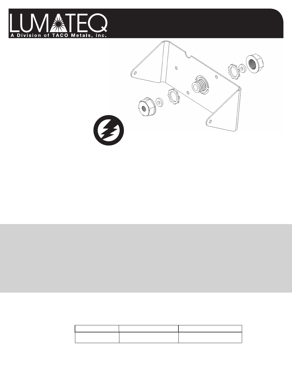
Plastic Cap Lock Nut
Washer
Metal Lock Nut
Metal Lock Nut
1/2" Threaded Nipple
Plastic Cap Lock Nut
Washer
Follow instructions carefully!
Wiring Instructions
Note: Always hire a licenced electrician for proper installation. Always mount this fixture to a grounded junction / breaker box.
Caution:
• Risk of Fire/Electrical Shock. If not qualified, consult an electrician.
• Disconnect power at fuse or circuit breaker before installing or servicing.
• Edges may cut. Handle with care.
1)
WARNING: Turn off the power at the main fuse or breaker box.
2)
Thread fixture wires through cover plate gasket and threaded nipple.
3)
Attach the ground wire from the fixture to the ground wire in the electrical box. If no ground is available attach fixture ground
wire to the junction box.
4)
All power connections should use approved wire nuts for the wire size. (We recommend using a good grade electrical tape
to insulate the wire nut connections before sealing the box.)
5)
•
110-120V AC wiring attach the Black wire from the fixture to the Black (Hot) wire in the box attach the White
wire from the fixture to the White (Neutral) in the box.
•
220-240V AC installations attach the Black wire from the fixture to the one of the Black (Hot) leads in the box
and then attach the fixtures White lead to the other Black (Hot) wire in the box.
•
277V AC Attach the Black lead from the fixture to the 277V (Hot) lead in the box and the White lead from the
fixture to the Neutral lead in the box.
Low Voltage Lights:
•
12-28V DC attach the Black lead from the fixture to the ground and the White lead from the fixture to the Switch
+ (Positive) lead.
•
12-28V AC Attach the Black lead to either of the two (2) incoming leads from the transformer and the White
to the other lead. Polarity is not a factor in this installation.
6)
Attach fixture to the junction box with two screws. Either (2) #6-32 or (2) #8-32 screws will work with most standard junction boxes.
If not mounting to a box, two holes are provided to flush mount to a smooth surface.
7)
Apply silicone caulk around the edge of the cover plate to provide a water tight seal from rain and moisture.
8)
Turn on power at main fuse or breaker box.
Troubleshooting
W
A
RN
ING!
Electrical
D
ev
ic
e
Tools Required
Make sure you have these items for fixture installation.
• Phillips Screwdriver
• Pliers
Required Items
(Purchase Separately)
:
• Silicone Caulking
• (3) Wire Nuts
Accessories
• Color-change kits available.
P
roblem
P
ossible
C
ause
C
orreCtive
a
Ction
Light does not come on
No power to the fixture
Wiring to the unit is loose
Check if circuit breaker is tripped
Confirm fixture is properly grounded
INSTRUCT
-BLASTER_10_40_60
Steel Bracket