ADC FPL Series User Manual
Page 34
ADCP-90-328 • Issue 2 • November 2005
Page 34
© 2005, ADC Telecommunications, Inc.
Reproduced by permission of 3M Company, from 3M Instruction Bulletin, Issue 1, dated February 1985, Number 43-7018-2209-9.
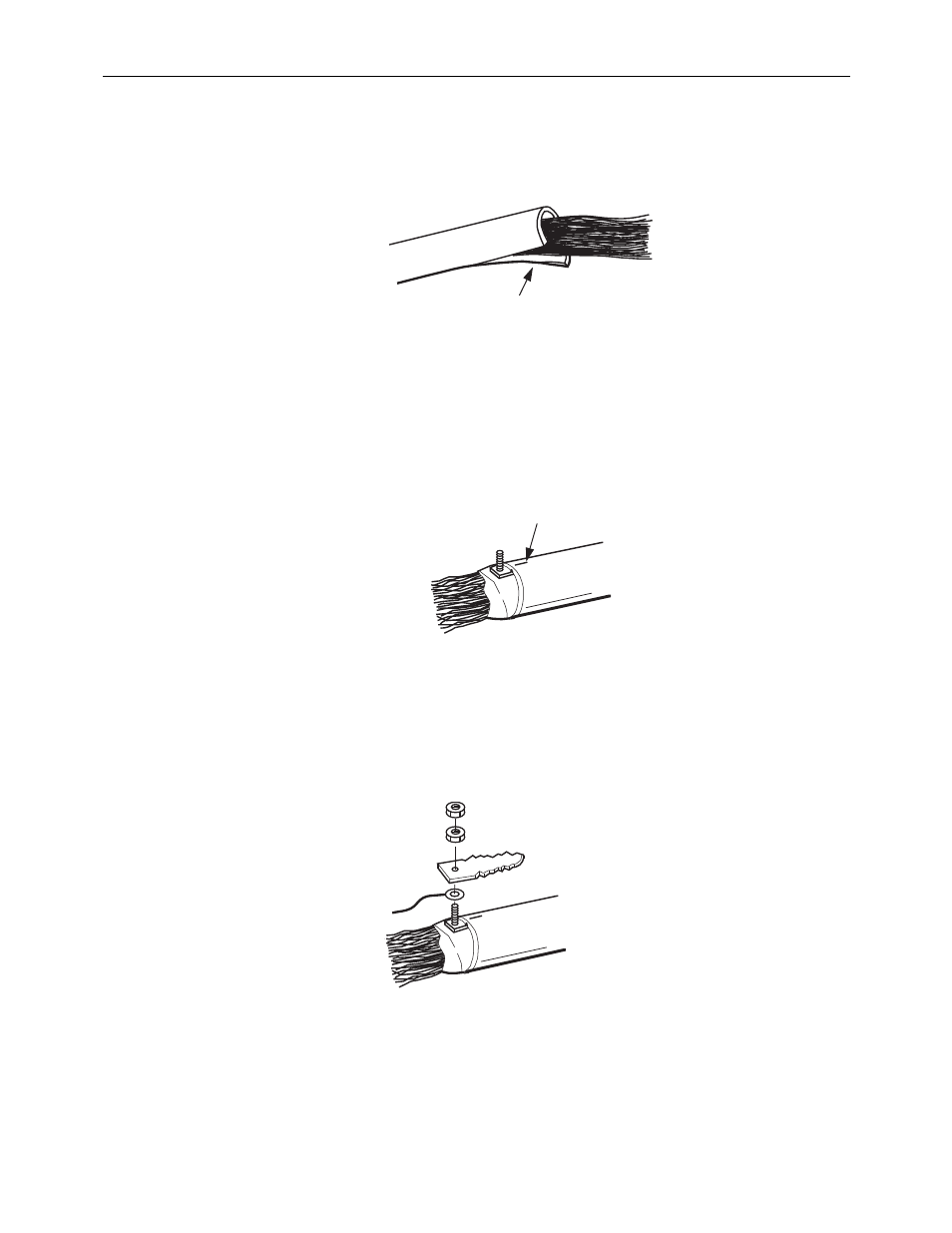
3. Make a one-inch cut in the cable sheath opposite the point at which the connector will be
attached as shown in
Figure 36. Cutting Cable Sheath
4. If installing single shield cable, insert connector base between shield and core wrap. If
installing double shield cable, insert connector base between shield and inner sheath.
5. Slide connector into cable until stops contact outer sheath. Tap on shield above connector
to set teeth.
Figure 37. Setting Connector Teeth
6. Install bonding wire on stud and place connector top over bonding wire. Do not tap on
connector top.
7. Install both nuts on connector as shown in
and tighten.
Figure 38. Bonding Wire Installation
1.0 IN. (25 mm)
9174-A
TAP HERE
9175-A
9176-A