Downdraft vent ei30dd10ks, Downdraft vent, Typical 30" downdraft vent /cooktop installation – Electrolux EI30DD10KS User Manual
Page 2: Electrolux major appliances, n.a, 30" downdraft vent dimensions, 30" downdraft vent/ cooktop countertop preparation, Electrical supply outlet installation
Electrolux Major Appliances, N.A.
USA
•
10200 David Taylor Drive
•
Charlotte, NC 28262
•
1-877-4electrolux (1-877-435-3287)
•
electroluxappliances.com
CANADA
•
5855 Terry Fox Way
•
Mississauga, ON L5V 3E4
•
1-800-265-8352
•
electroluxappliances.ca
EI30DD10K 07/12
© 2012 Electrolux Home Products, Inc.
High standards of quality at Electrolux Home Products, Inc. mean
we are constantly working to improve our products. We reserve the right
to change specifications or discontinue models without notice.
Downdraft Vent
EI30DD10K S
Downdraft Vent Specifications
•
Downdraft Vent requires installation with Blower Motor System Kit –
1600 CFM Remote option or 600 CFM Integrated option (kit ordered
separately). Vent ships with transition duct pre-attached to chassis housing
for Remote Blower Motor installation and is removable for Integrated Blower
Motor installation. For Blower Motor System planning information, refer
to specific kit’s specifications page; for complete installation details and
specifications, refer to specific Product Installation Guides on web.
•
Voltage Rating – 120V / 60 Hz / 15 Amps
•
Connected Load (kW Rating) and Amps @ 120 Volts – Refer to specific
Blower Motor System Kit specification page.
•
Do not use same circuit as cooktop.
•
Always consult local and national electric codes. Check local building
codes for installation requirements, as they may vary per locale.
•
Locate grounded electrical outlet for 28"- long power cord within reachable
distance. When installing vent in 30"- wide cabinet, outlet cannot be
located on back wall of cabinet, but can be wall-mounted with access
hole in cabinet.
•
Downdraft Vent designed for installation with cooktop in island, peninsula
or conventional installation. (Cutout template provided, packed with vent.)
•
To ensure proper installation with cooktop, refer to model-specific
cooktop installation guide on web for dimensions, countertop cutout
dimensions and cabinet requirements; oversized cabinets recommended
for ease of installation. Due to varying cooktop depths, tight fit is possible
between cooktop and vent, depending on overall depth of countertop.
•
Pre-formed countertops with raised lip and /or backsplash may not
allow enough flat area for proper installation. Minimum 2-5/16" of flat
countertop required behind cooktop and 2-1/16" necessary between
back edge of cooktop and inside of cabinet back.
•
To ensure adequate clearance for air vent when raised /lowered, 1/8" gap
needed between back edge of cooktop and front of downdraft top trim.
•
Vent exhaust air outside only.
•
Exhaust Duct Required – Refer to specific Blower Motor System Kit
specifications page.
•
Three blower discharge direction options available. Pre-positioned with
discharge facing down; left or right discharge requires 90-degree transition
duct rotation. Transition duct can also be mounted to back of chassis
housing with minimum 3-3/4" clearance to back of cabinet wall.
•
Consider ductwork location before cutting hole in cabinet.
•
For maximum efficiency, use shortest and straightest duct run possible.
System operates most efficiently with up to 60 equivalent feet of duct;
Downdraft Vent operates properly with ductwork up to 100 equivalent
feet. (Refer to Calculating Duct Length Table in Product Installation Guide.)
•
Do not use flexible duct. Round duct instead of rectangular duct
recommended, especially when elbows are required.
•
Thermal breaks such as short section of nonmetallic duct, should be used
in areas of extreme cold. Cold weather installations should have additional
backdraft damper installed.
•
High level of airflow may affect gas flame on some gas cooktop models.
Blower Motor System Options
•
1600 CFM Remote Blower Motor System Kit – (PN # EI16DDPRKS).
•
600 CFM Integrated Blower Motor System Kit – (PN # EI06DDPIKS).
Note: For planning purposes only. Refer to Product Installation Guide
on the web at electroluxappliances.com for detailed instructions.
Maximum 4
1
/
2
"gap allowed between inside cabinet
back and chassis BEFORE downdraft stabilizing brackets
will require wood support installation for mounting
* For minimum clearance,
refer to specific Blower
Motor Kit specifications.
1
/
4
"min.
†
2
5
/
16
"
Front to back
inside cabinet depth
1
/
8
"
(A)Countertop
raised lip
(B)
Countertop
backsplash
Downdraft
top trim
Cooktop
†
Clearance
required
behind
downdraft
top trim
Transition duct
(or Integrated Blower Motor)
Min. clearance*
Downdraft
chassis
housing
2
1
/
16
"
Downdraft Vent
EI30DD10KS
Blower Motor System Kit Options: Downdraft Vent requires installation with
Blower Motor System Kit – 1600 CFM Remote option or 600 CFM Integrated option
(kit ordered separately). Vent ships with transition duct pre-attached to chassis
housing for Remote Blower Motor installation and is removable for Integrated
Blower Motor installation. For Blower Motor System planning information, refer to
specific kit’s specifications page; for complete installation details and specifications,
refer to specific Product Installation Guides on web.
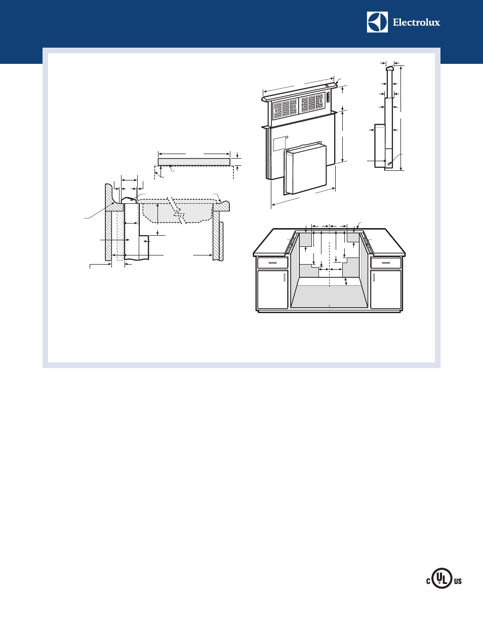
Typical 30" Downdraft Vent /Cooktop Installation
Designed for use with cooktop in conventional, island or peninsula installation.
Downdraft Vent requires installation with Blower Motor System Kit.
30" Downdraft Vent Dimensions
with Transition Duct (for Remote Blower
Motor installation option)
**Only used for vent installation
with remote blower option.
Discharge pre-positioned down;
left or right discharge requires
90-degree duct rotation.
30" Downdraft Vent/
Cooktop Countertop
Preparation
Cooktop edges
26
15
/
16
"
2
1
/
16
"
30" Downdraft Vent cutout
Countertop Cutout Dimensions
(Cutout template provided, packed with vent.)
Top
View
Cooktop Installation Notes: To ensure
proper installation, refer to model-
specific cooktop installation guide on
web for dimensions, countertop cutout
dimensions and cabinet requirements;
oversized cabinets recommended
for ease of installation. Due to varying
cooktop depths, tight fit is possible
between cooktop and vent, depending
on overall depth of countertop.
Countertop Preparation Notes: Pre-formed
countertops with (A) raised lip and/or
(B) backsplash may not allow enough flat
area for proper installation. Minimum
2-5/16"of flat countertop required behind
cooktop and 2-1/16"necessary between
back edge of cooktop and inside of cabinet
back. To ensure adequate clearance for
air vent when raised/lowered,1/8"gap
needed between back edge of cooktop
and front of downdraft top trim.
30"
17
13
/
16
"
10"
Rise
26
7
/
8
"
Transition
duct**
(with 3-way
ducting)
Top trim
Chassis
housing
2
3
/
16
"
35
13
/
16
"
5
9
/
16
"
2
1
/
4
"
1
7
/
16
"
Control
box
Power
cord
2
1
/
2
"
Electrical Supply Outlet Installation
for 30" Downdraft Vent
Electrical Installation Notes: All vertical dimensions relative to top
surface of countertop; all horizontal dimensions relative to cutout in
countertop. Locate grounded electrical outlet for 28"-long power cord
within reachable distance. When installing vent in 30"-wide cabinet,
outlet cannot be located on back wall of cabinet, but can be wall-mounted
with access hole in cabinet. Ensure that access to outlet will NOT be
obstructed by ducting after installation.
19
1
/
16
"
CL
Mount 120 VAC grounded
outlet inside cabinet, confined
to shaded area.
7
7
/
8
" 8
3
/
4
"
14
3
/
4
"
Cabinet
side wall
Cabinet
side wall
6
1
/
2
"
22
1
/
8
"
23
3
/
4
"
4
5
/
8
"
9
1
/
2
"
13
1
/
2
"
Countertop surface
13
1
/
2
"