Allied Air Enterprises 92G1DF User Manual
Page 31
506503-01
Page 31 of 44
Issue 1031
One line voltage “HUM” 1/4” spade terminal is provided on
the furnace control board. Any humidifier rated up to one
amp can be connected to this terminal with the neutral leg
of the circuit being connected to one of the provided neutra
terminals. If a humidifier rated at greater than one amp is
connected to this terminal, it is necessary to use an external
relay. See Figure 49 for control board configuration. This
terminal is energized in the heating mode when the
combustion air inducer is operating.
Install the room thermostat according to the instructions
provided with the thermostat. See Figure 46 for thermostat
designations. If the furnace is being matched with a help
pump, refer to the FM21 installation instruction or appropriate
dual fuel thermostat instructions.
Indoor Blower Speeds
1.
When the thermostat is set to “FAN ON”, the indoor
blower will run continuously on the heating speed when
there is no cooling or heating demand.
2.
When the furnace is running in the heating mode, the
indoor blower will run on the heating speed.
3.
When there is a cooling demand, the indoor blower will
run on the cooling speed.
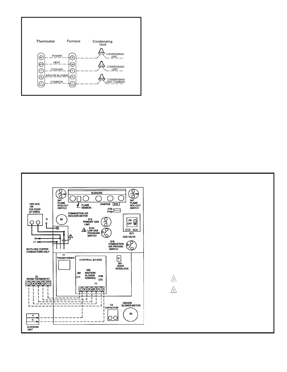
FURNACE & CONDENSING UNIT
THERMOSTAT DESIGNATIONS
(Refer to specific thermostat and outdoor unit.)
Figure 46
NOTE: Required on some outdoor units.
TYPICAL FIELD WIRING DIAGRAM
Figure 47
WARNING:
ELECTRIC SHOCK HAZARD, CAN CAUSE INJURY
OR DEATH. UNIT MUST BE GROUNDED IN
ACCORDANCE WITH NATIONAL AND LOCAL CODES
NOTE:
IF ANY WIRE IN THIS APPLIANCE IS REPLACED, IT
MUST BE REPLACED WITH WIRE OF LIKE SIZE,
RATING, INSULATION THICKNESS AND
TERMINATION
FIELD SUPPLIED ACC. WIRE
S145 IS USED WITH HONEYWELL GAS VALVE
WHEN APPLIED IN LP GAS UNITS
Accessory Terminals
One line voltage “EAC” 1/4” spade terminal is provided on
the furnace control board. Any accessory rated up to one
amp can be connected to this terminal with the neutral leg
of the circuit being connected to one of the provided neutral
terminals. If an accessory rated at greater than one amp is
connected to this terminal, it is necessary to use an external
relay. See Figure 49 for control board configuration. This
terminal is energized when the indoor blower is operating.