Allied Air Enterprises 92G1DF User Manual
Page 24
506503-01
Page 24 of 44
Issue 1031
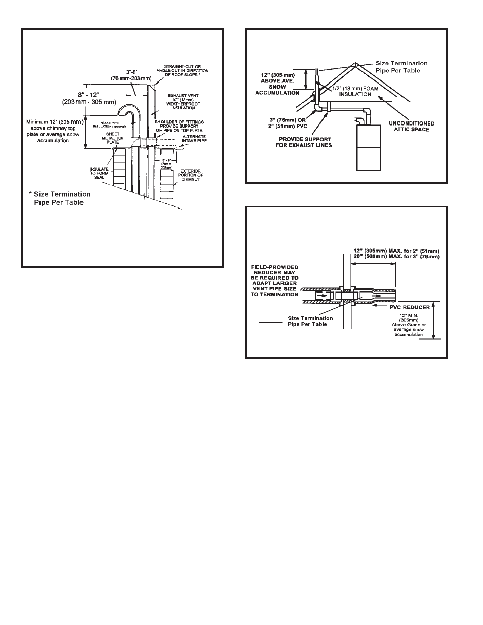
Details of Exhaust Piping Terminations for Non-Direct
Vent Applications
Exhaust pipes may be routed either horizontally through an
outside wall or vertically through the roof. In attic or closet
installations, vertical termination through the roof is preferred.
Figures 33 through 34 show typical terminations.
1.
Exhaust piping must terminate straight out or up as
shown. The termination pipe must be sized as listed in
Table 8. The specified pipe size ensures proper velocity
required to move the exhaust gases away from the
building.
2.
On field supplied terminations for side wall exit, exhaust
piping may extend a maximum of 12 inches (305 mm)
for 2” PVC and 20” (508 mm) for 3” (76 mm) PVC beyond
the outside wall. See Figure 35.
3.
If exhaust piping must be run up a sidewall to position
above snow accumulation or other obstructions, piping
must be supported every 24” (610 mm) as shown in
Figure 36. When exhaust piping must be run up an
outside wall, any reduction in exhaust pipe size must be
done after the final elbow.
DIRECT VENT APPLICATION
USING EXISTING CHIMNEY
NOTE: Do not discharge exhaust gases directly into any chimney
or vent stack. If vertical discharge through an existing unused chim-
ney or stack is required, insert piping inside chimney until the pipe
open end is above top of chimney and terminates as illustrated. In
any exterior portion of chimney, the exhaust vent must be insulated.
Figure 33
NON-DIRECT VENT ROOF TERMINATION KIT
(15F75 or 44J41)
Figure 34
NON-DIRECT VENT FIELD SUPPLIED WALL
TERMINATION
Figure 35