Electrical diagram bti – A.O. Smith BTI - 65 User Manual
Page 6
www.aosmithinternational.com
Data subject to change INT/0808/BTI/01
Terms and conditions apply
, please refer to our website.
BTI
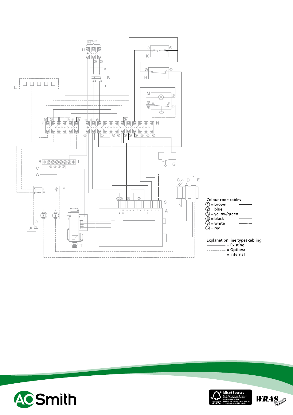
Electrical diagram BTI
A
Ignition controller
B
ON/OFF switch
C
Pilot burner
D
Spark electrode
E
Flame probe
F
Transformer flame detection
(optional)
G
Combustion products discharge
safety device
H
Control thermostat
K
Safety thermostat
L
Timer (optonal)
M
Remote button
N
Terminal block
P
Terminal block
R
Earth terminals
S
Connector to ignition controller
T
Gas control valve
U
Connection strip
V
Tank earth
W
Casing earth
X
Control panel base plate earth
For the parts numbers of components
please refer to the “Maintenance and
accessories” chapter.