Installation diagram – A.O. Smith BTI - 65 User Manual
Page 5
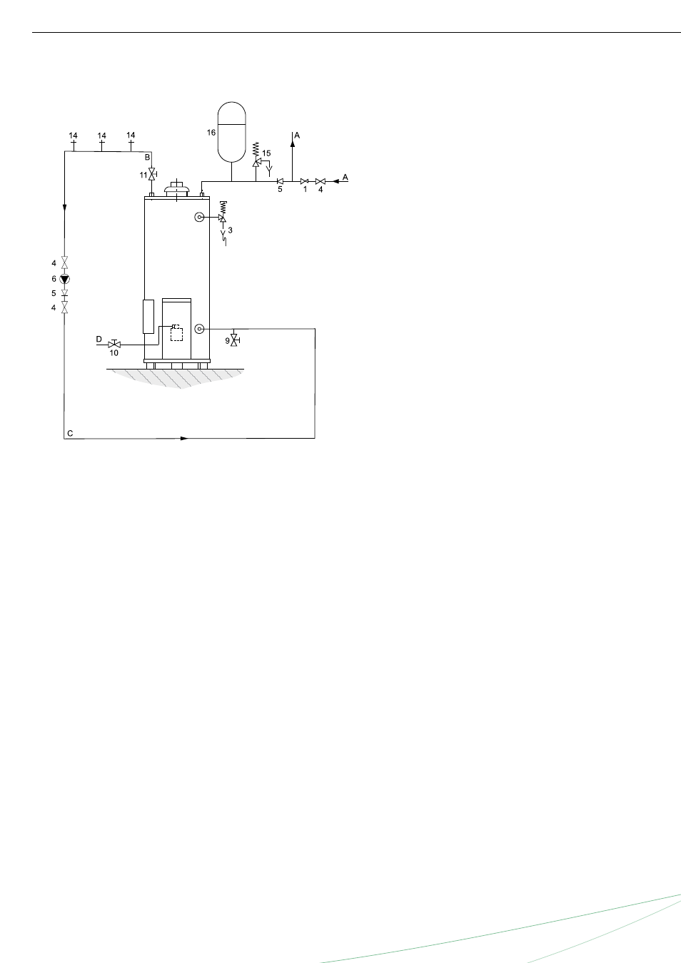
BTI
Installation diagram
Unvented
1 Pressure reducing valve
3 T&P valve
4 Stop valve
5 Non-return valve
6 Circulation pump
9 Drain valve
10 Gas cock
11 Isolating valve
14 Hot water outlets
15 Expansion relief valve
16 Expansion vessel
A Cold water
B Hot water
C Return circulation
D Gas supply
A.O. Smith unvented system kits utilise combination valves.
A water heater should be installed in accordance with
local standards and ventilation requirements (category B11BS).
Further installation and connection details can be found in
the Installation & Commissioning Manual.