Aiwa CDC-Z107 User Manual
Page 26
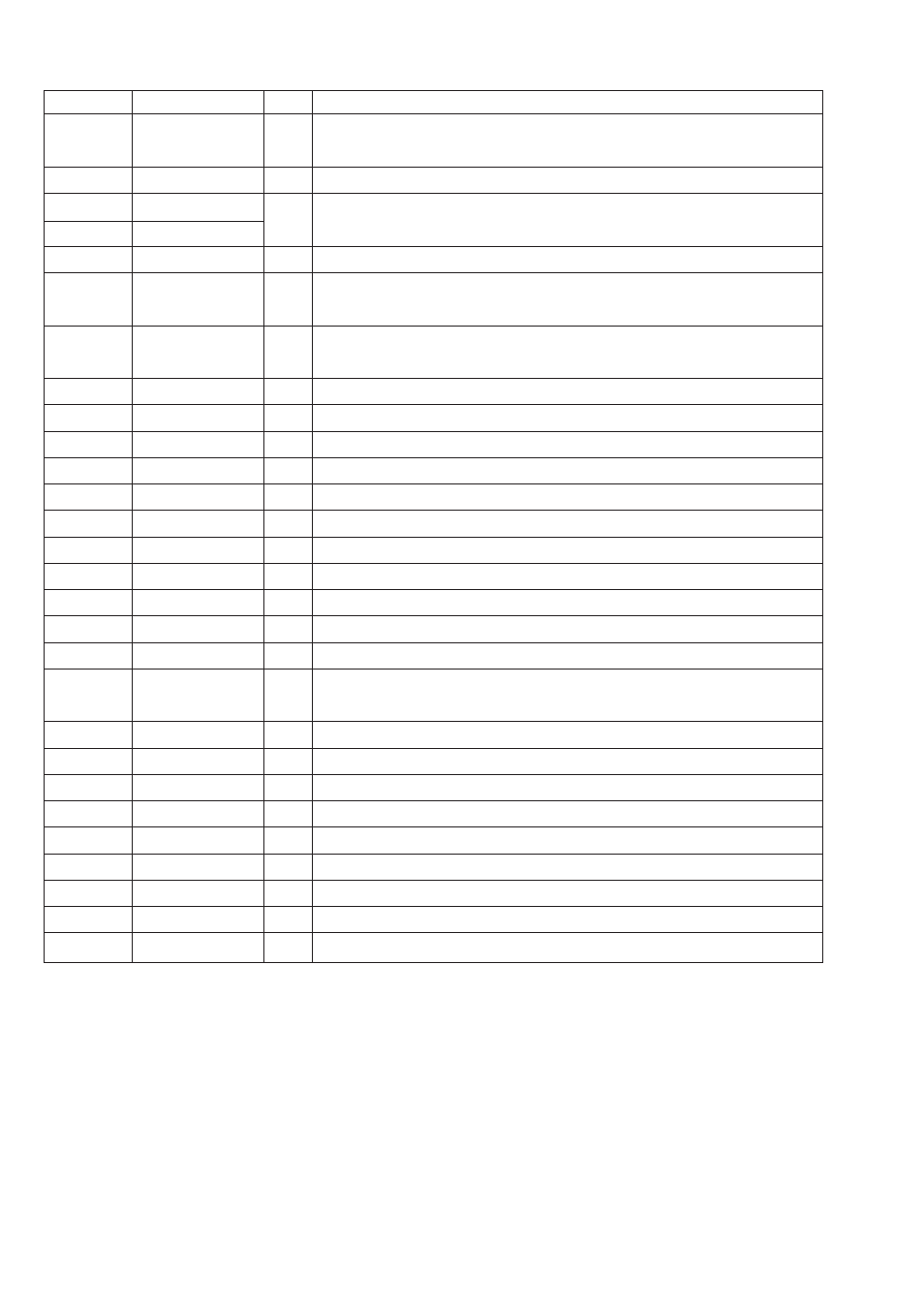
Pin No.
Pin Name
I/O
Description
37
HFL
O
The HFL (high frequency level) signal is used to judge whether the main beam is
positioned on the pit or on the mirror.
38
SLOF
I
Sled servo off control input.
39
CV-
I
CLV error signal input from the DSP.
40
CV+
41
RFSM
O
RF output.
42
RFS-
O
Sets the RF gain and the EFM singal's 3T compensation constant togther with the
RFSM pin.
43
SLC
O
The SLC (slice level control) signal is output to control the DSP's data slice level of the
RF waveform.
44
SL1
I
Input to control the DSP's data slice level.
45
D-GND
-
Ground of digital signals.
46
FSC
O
Output for the focus search smoothing capacitor.
47
TBC
I
The TBC (tracking balance control) signal sets the EF balance variation range.
48
NC
-
Not connected.
49
DEF
O
Disc defect detection output.
50
CLK
I
Reference clock input. 4.23 MHz is input from the DSP.
51
CL
I
Microprocessor command clock input.
52
DAT
I
Microprocessor command data input.
53
CE
I
Microprocessor chip enable input.
54
DRF
O
DRF (detect RF) is an output to detect the RF level.
55
FSS
I
The FSS (focus search select) signal switches the focus search modes (+/-search /
+search with respect to the reference voltage). (Not connected)
56
VCC2
-
VCC of servo and digital circuits.
57
REF1
-
For the connection of bypass capacitor for the reference voltage.
58
VR
O
Reference voltage output.
59
LF2
-
Sets the time constant for disc defect detection.
60
PH1
-
For the connection of a capacitor to hold the RF signal peak.
61
BH1
-
For the connection of a capacitor to hold the RF signal bottom.
62
LDD
O
APC circuit output.
63
LDS
I
APC circuit input.
64
VCC1
-
VCC of RF signal circuits.
- 26 -