UEi Test Instruments DM393 User Manual
Page 5
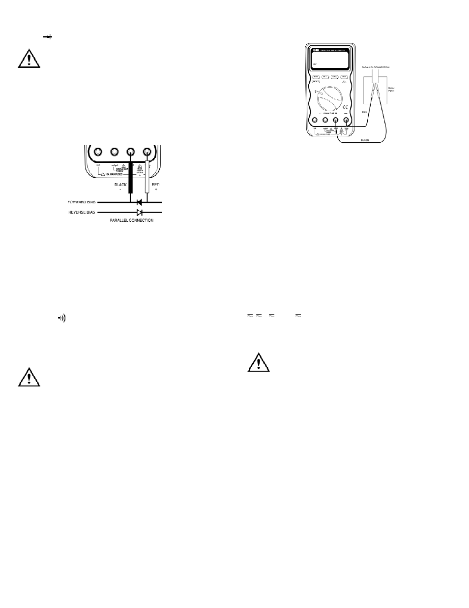
Diode ( ) Test
CAUTION!
Discharge all high-voltage capacitors before testing diodes. Large
value capacitors should be discharged through an appropriate
resistance load.
Use the diode test to check diodes, transistors, silicon controlled rectifiers
( S CRs), and other semiconductor devices. The test sends a current through
a semiconductor junction, then measures the junction’s voltage drop.
Normal forward voltage drop (forward biased) for a good silicon diode
is between 0.4V to 0.9V. A reading higher than that indicates a leaky
(defective) diode. A zero reading indicates a shorted (defective) diode.
An “OL” indicates an open (defective).
Reverse the test leads connections (reverse biased) across the diode.
The display shows “OL” if the diode is good. Any other readings
indicate the diode is shorted or resistive.
Continuity ( ) Test
The continuity function detects intermittent opens and shorts lasting as
little as 1 millisecond. These brief contacts cause the meter to emit a short
beep. This function is convenient for checking wiring connections and
o p e ration of switches. A continuous beep tone indicates a complete wire.
CAUTION!
Using resistance and continuity function in a live circuit will produce
false results and may damage the instrument. In many cases the
suspicious components must be disconnected from the circuit under
test to obtain accurate results.
Frequency (Hz) Measurement
Fr e q u e n cy is the number of cycles a signal completes each second. The
meter measures the frequency of a voltage or current signal by counting
the number of times the signal crosses a threshold level each second. To
measure the frequency of a voltage or current signal, press the “H z /D u t y”
push-button momentarily while measuring volts or currents.
The available frequency ranges are: 5Hz, 50Hz, 500Hz, 5kHz, 50 k H z ,
500kHz, 5MHz, and 10 MH z .
Tips for Measuring Frequency
• In frequency, the meter is always autoranging
• When disconnecting the input terminals, the overload sign may be
displayed or the display may unsteadily fluctuate - This is typical
Duty Cycle Measurement
D u ty Cycle (or Duty Factor) is the percentage of time a signal is above or
b e l ow a trigger level during one cycle. The duty cycle mode is optimized
for measuring the ON or OFF time of logic and switching signals. Sy s t e m s
such as electronic fuel injection systems and switching power supplies are
controlled by pulses of varying width, which can be checked by measuring
d u ty cy c l e .
Press the “Hz/Duty” push-button to toggle between the Hz mode and the
D u ty Cycle mode when the rotary selector knob is set to “Hz” (Duty),
V, µA, mA, and 10A.
Capacitance Measurement
CAUTION!
To avoid damaging the meter or the equipment under test, remove all
power from the circuit and discharge all high-voltage capacitors before
measuring capacitance. Large value capacitors should be discharged
through an appropriate resistance load. Use the DC voltage function to
confirm that the capacitor is discharged.
Capacitance is the ability of a component to store an electrical charge.
The unity of capacitance is the farad (F). Most capacitors are in the
nanofarad (nF) to microfarad (µF) range.
The available capacitance ranges are 40nF, 400nF, 4µF, 40µF, and 10 0 µ F.
DM391/393-MAN
P. 4