UEi Test Instruments DM393 User Manual
Page 4
Operating Instructions
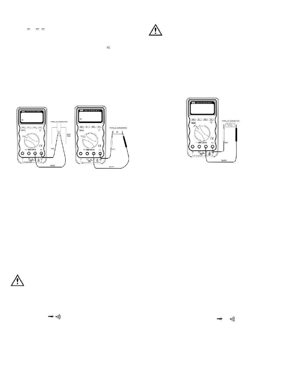
Voltage (V or V, V) Measurements
Voltage is the difference in electrical potential between two points. The
p o l a r i ty of AC (alternating current) voltage varies over time, while the
p o l a r i ty of DC (direct current) voltage is constant over time. V function
defaults at DC. Press the “SEL ECT” push-button momentarily to select AC .
Range available in volts function are:
400mV, 4V, 40V, 400V, and 1000V
When measuring voltage, the meter acts like a 10MΩ (10 x 10˚Ω)
impedance in parallel with the circuit. This loading effect can cause
measurement errors in high impedance circuits. In most cases, the
error is negligible (0.1% or less) if the circuit impedance is 10kΩ or less.
Tips for Measuring Voltage
• In 400mV range, displayed value may fluctuate while disconnecting
input terminals - This is normal
• AC voltage measuring circuit in DM393 is of root-mean-square
(True RMS) value systems so the meter can accurately measure
AC voltage of non-sinusoidal waveforms including harmonics
caused by various non-linear loads
• To improve the accuracy of DC voltage measurement taken in the
presence of AC voltages (such as, measuring the DC voltage of an
amplifier in the presence of an AC signal), measure the AC volt
age first. Note the just measured AC voltage range and select a
DC voltage rage that is the same or higher than the AC voltage
range - This method improves the DC voltage accuracy by
preventing the input protection circuits from being activated.
WARNING!
To avoid the risk of electrical shock and instrument damage, input
voltages must not exceed 1000 V DC or AC (RMS). Do not attempt to
take any unknown voltage measurement that may be in excess of
1000 V DC or AC (RMS).
Resistance (Ω, , ) Measurement
(Ohms, Diode, and Continuity)
DM391/393-MAN
P. 3
WARNING!
To avoid damaging the meter or the equipment under test, remove all
power from the circuit and discharge all high-voltage capacitors before
measuring resistance.
Resistance is an opposition to current flow. The unit of resistance is the
ohm (Ω). The meter measures resistance by sending a small current
through the circuit.
Ranges available in resistance functions are:
4000.0Ω, 4.000 kΩ, 40.00 kΩ, 400.0 kΩ, 4 MΩ, and 40 MΩ
Tips for Measuring Resistance
• Because the meters test current flows through all possible paths
between the test prove tips, the measured value of a resistor in a
circuit is often different from the resistor’s rated value
• The test leads can add 0.1Ω to 0.2Ω of error to resistance
measurements - To measure the resistance of the leads, touch the
probe tips together and read the resistance - If necessary, you can
press the “REL∆” push-button to automatically subtract this value
• The resistance function can produce enough voltage to
forward-bias silicon diode or transistor junctions, causing them to
conduct - Do not use the 40 MΩ range for measuring the in-circuit
resistance to avoid this
• When measuring large resistance, reading may be unstable due to
environmentally induced electrical noise - In this case, directly
connect the resistor to input terminals of the meter or shield the
resistor at potential of the “COM” input terminal to obtain
stable reading
• For resistance above 1 MΩ, the display may take a few seconds
to stabilize - This is normal for high resistance readings
• The meter has a circuit to protect the resistance range from
over-voltage - However, to prevent accidentally exceeding the
protection circuit’s rating and to ensure a correct measurement,
NEVER CONNECT THE LEADS TO A SOURCE OF VOLTAGE
when the rotary switch is set to Ω, , or functions