Trio Motion Technology CAN 8 Relay Out User Manual
Quick connection guide, Can 8-relay out module (p327), Can i/o modules
(Please refer to the Motion Coordinator Technical Reference Manual 7 for Full Details)
CAN I/O MODULES
Quick Connection Guide
LED Indicators
Bus
Connections
DIP Switch
I/O Connections
Quick Start v5.0 March 2011
Trio Motion Technology Ltd.
[email protected]
Trio Motion Technology LLC
[email protected]
Trio Shanghai
[email protected]
Trio India
[email protected]
Website: www.triomotion.com
All trade marks acknowledged.
LED ERROR
CODES
When an error occurs on a CAN I/O module, the ERR LED will be
lit and the fault code is represented by a binary number displayed
on the leds.
Code
Error Description
1
Invalid Protocol
2
Invalid Module Address
3
Invalid Data Rate
4
Uninitialised
5
Duplicate Address
6
Start Pending
7
System Shutdown
8
Unknown Poll
9
Poll Not Implemented
10
CAN Error
11
Receive Data Timeout
ERR
8
9
10
11
12
13
14
15
0
1
2
3
4
5
6
7
PWR
Error Code
displayed on
IO 8 .. 11
Whole Bank
Flashing
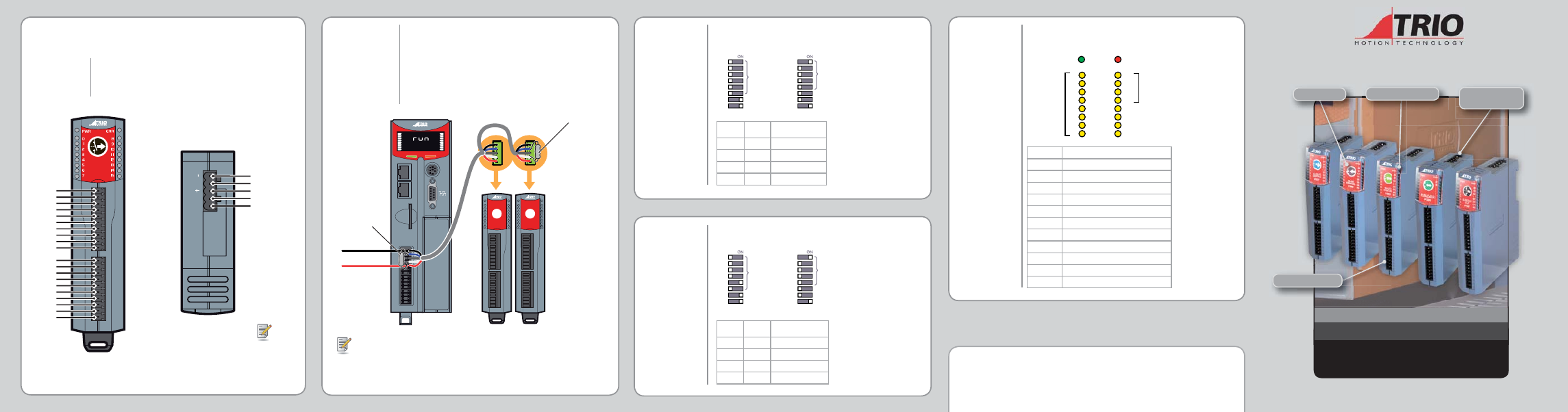
BUS WIRING
DIP SWITCH
SETTINGS
P317, P318,
P319, P327
Trio mode module addresses must be set in sequence with no
gaps starting at address 0.
DIP SWITCH
SETTINGS
P326
Trio mode module addresses must be set to 16...19.
Address
(Trio Mode)
N/A
1
2
4
8
16
32
PR
DR
1
2
4
8
16
32
PR
DR
Address
DR B0
(CANopen Mode)
DR B1
Trio Mode
CANopen Mode
1
2
4
8
16
32
PR
DR
1
2
4
8
16
32
PR
DR
Trio Mode
CANopen Mode
Address
(Trio Mode)
N/A
Address
DR B0
(CANopen Mode)
DR B1
DR B1
DR B0 Data Rate Bit/s
0
0
125K
0
1
250K
1
0
500K
1
1
1M
DR B1
DR B0 Data Rate Bit/s
0
0
125K
0
1
250K
1
0
500K
1
1
1M
The CAN I/O modules and the Motion Coordinator are connected
together on a CAN network. Terminate both ends of the network
with 120Ω, 1/4W, 1% metal fi lm resistors between CAN_H and
CAN_L.
The CAN I/O modules are powered from the network. The 24V
supply for the network must be externally connected. The
Motion Coordinator does NOT provide the network power.
Use recommended CANbus specifi cation cables.
101011
A
B
0
1
2
3
4
5
6
7
8
9
10
11
12
13
14
15
ENABLE
MC 464
7HUPLQDWLQJ
Resistor
7erPiQDtiQJ
Resistor
93oZer6XSSO\
to1etZorN
P317 / P319 - It is recommended that you use a separate power supply from that
used to power the digital outputs to power the network as switching noise from
the I/O devices may be carried into the network.
CONNECTIONS
CAN 8-Relay Out Module (P327)
8-RELAY
OUT
P327
0
1
2
3
4
5
6
7
24V
0V
8
9
10
11
12
13
14
15
24V
0V
Com0
NO0
NC0
Com1
NO1
NC1
Com2
NO2
Com3
NO3
Com4
NO4
NC4
Com5
NO5
NC5
Com6
NO6
Com7
NO7
V- (black)
CAN_L (blue)
Shield
CAN_H (white)
V+ (red)
- L H +
24V DC Class 2
V+ = 24V
V- = 0V
Power supply: 24V dc Class 2 transformer or power supply. +/-20%
Max switching voltage: 30V dc, 49V ac
Absolute Max current: 1Amp
Max switching power: 62.5 VA, 24W (dc)
Isolation outputs / CAN: 1,500V dc