Electrical connections, Unit and for the control system – ROTRONIC CF3-W-EU-FLI User Manual
Page 2
Dokument
IMA 205
Rev
1
Page
2 (4)
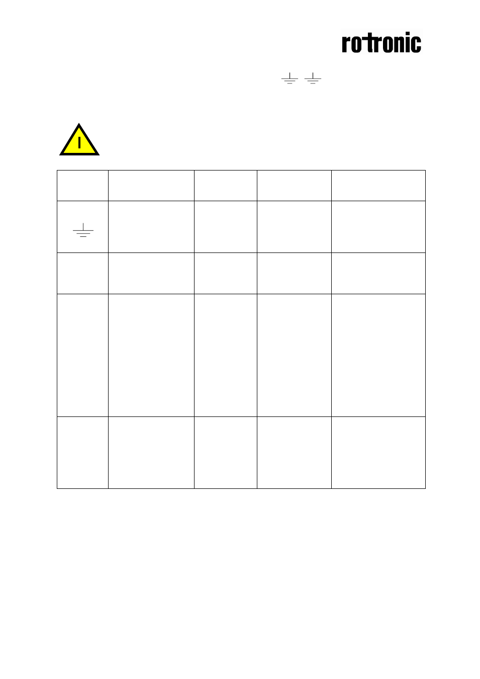
Electrical connections
The power supply has to be connected to
+~
and
.
is considered as system
ground. The same ground reference has to be used for the CF3-W-EU-Disp-FLI unit
and for the DDC/signal receiver.
PLEASE NOTE!
The same ground reference has to be used for the CF3-W-
EU-Disp-FLI
unit and for the control system!
Terminal
Function
Electrical
data
Remarks
Standard
settings
Remarks
Settings of this
sensor
+~
Power (+)
Power ground (-)
24 VAC/DC+
(+-20%), 2W
24 VAC/DC-
System voltage
reference
Out(1)
Out(2)
Analogue output 1
(+)
0-10 VDC
0-2000 ppm CO
2
Buzzer connected
Green LED
Yellow
LED
Red LED
Lit when the CO
2
concentration is below
800 ppm
Lit when the CO
2
concentration is 800
to 1400 ppm
Lit when the CO
2
concentration is
above 1400 ppm
The buzzer sounds
Push
button
Silences the buzzer
30 minutes when
pushed. After 30
minutes the buzzer
sounds if the CO
2
concentration is
above 1400 ppm
Table I. Connections of the main terminal and other functions of CF3-W-EU-Disp-FLI