Installation continued, Operation, Figure 5 – ProMariner TruePower 400PS User Manual
Page 10
11
8
I n s t a l l a t i o n G u i d e l i n e s
INSTALLATION CONTINUED
6
. Check that the polarity of the DC connections are correct: RED to positive (+) at
the battery and BLACK to negative (-) at the battery.
7
. Replace the fuse and/or switch on the breaker. A small spark is normal when this
connection is made.
Hardwiring the AC Output:
WARNING
: Fire, Shock and Energy Hazards
Make sure wiring is disconnected from all electrical sources before handling. All
wiring must be done in accordance with local and national wiring codes. Do not
connect the output leads of the inverter to any incoming AC source.
To Hardwire the AC Output Connections:
1
. Turn the inverter On/Off switch to Off.
2
. Locate the wiring box access panel, and remove the two screws to access the
wiring box as illustrated in Figure 5.
Figure 5 ~ Removing the Two Screws on the Wiring Box Access Panel
3
. Remove the wiring box access panel from the unit.
4
. Loosen the clamping nut of the Strain Relief.
5
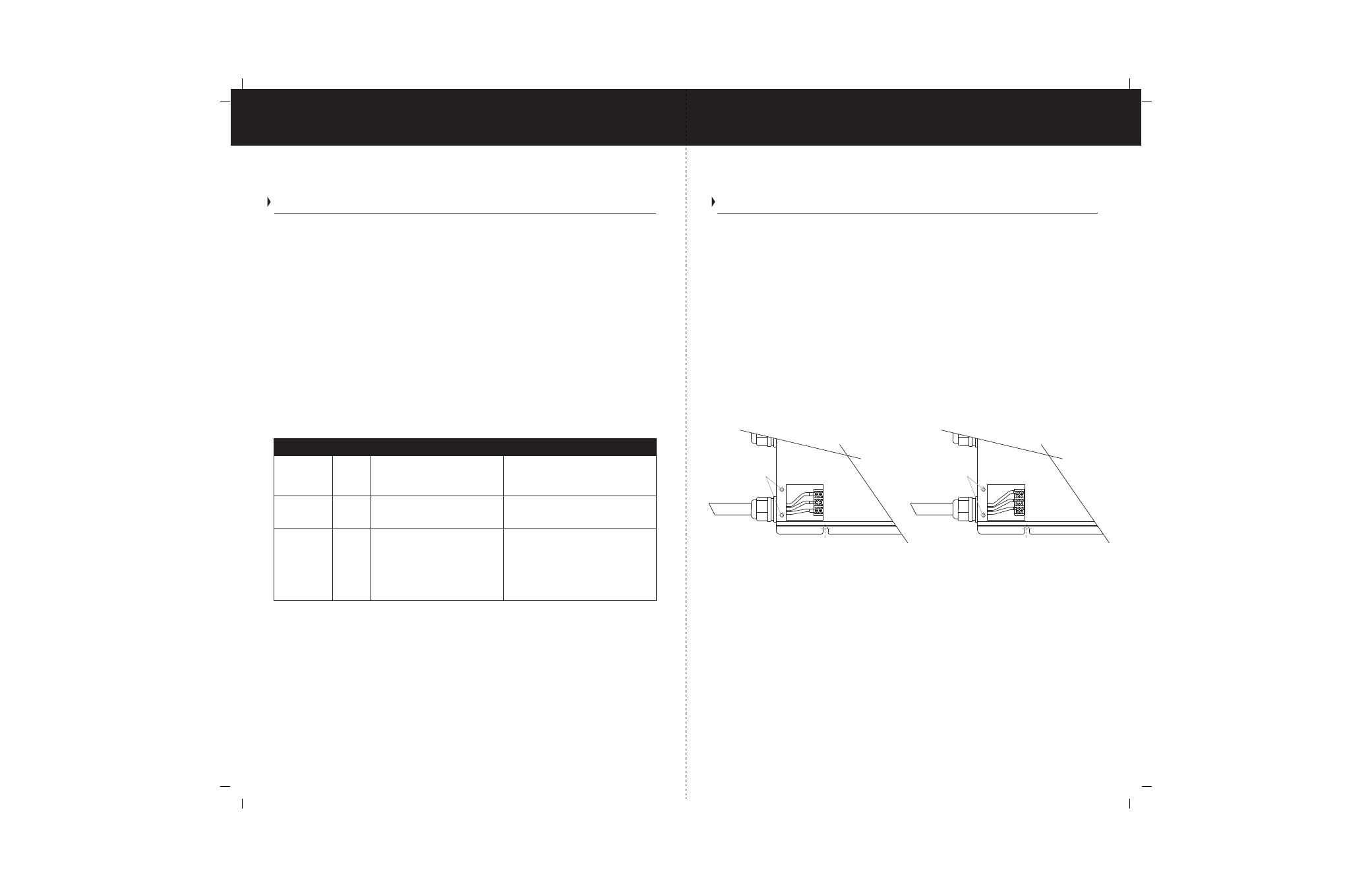
. Locate the terminal block.
The three terminals are labeled as follows;
- L Line
- N Neutral
- G Ground
6
. Strip about 2 inches off the jacket of the AC output cable. The AC output cable
must be with in range of No. 14 to No. 16 AWG, have three conductors and be solid
or stranded.
G e n e r a l O p e r a t i o n
OPERATION
The ON/Off switch turns the TruePower400 PS to ON or to Off.
- In the ON position, the Inverter / Fault LED light will illuminate Green. The TruePower400PS
begins inverting and provides 400 watts of sine wave power, if shorepower is not present.
- In the Off position with no shorepower present, the TruePower400PS draws no current
from the battery.
- In the Off position with the AC input cord plugged into shorepower, the AC Input LED
light illuminates Green and the appliances connected to the TruePower400PS inverter
can be operated.
NOTE: When the ON/Off switch is in the Off position with the TruePower400PS
connected to shorepower, AC voltage will be present at the output.
LED Indicators: The two indicator lights on the front panel of the inverter illustrate the
operating status of the TruePower400PS. See table 4 below.
Table 4 ~ Status of Indicator Lights
Can not run appliances as the AC
output is disabled in the invert mode.
Clear the fault condition. Reset the
TruePower400PS by turning the ON/Off
switch to Off and then back to ON, or
by connecting to shorepower.
Shorepower
ON
When the TruePower400PS is
connected to shorepower, the AC
Input illuminates.
Green
Can run all your appliances from
shorepower.
Inverter/Fault
Green
When the TruePower400PS unit
is on, the Inverter light illuminates.
Can run your appliances through the
TruePower400PS from the battery.
Inverter/Fault
Red
The Fault light illuminates
whenever there is a battery over-
voltage fault condition (in excess
of 15.6 volts), an output overload
condition or over-temperature
fault condition.
Light
Color Status
Result
Solid Wire
L
Line
Neutral
Ground
Access screw location
AC OUTPUT WIRING
N
G
14 or 16 ga.
3 conductors
Solid
Stranded Wire
Access screw location
Figure 5
Ground
Neutral
Line
14 or 16 ga.
3 conductors
Stranded
L
G
N
AC OUTPUT WIRING