I n s ta l l at i o n, Promar1 wiring diagrams – ProMariner ProMar1 User Manual
Page 8
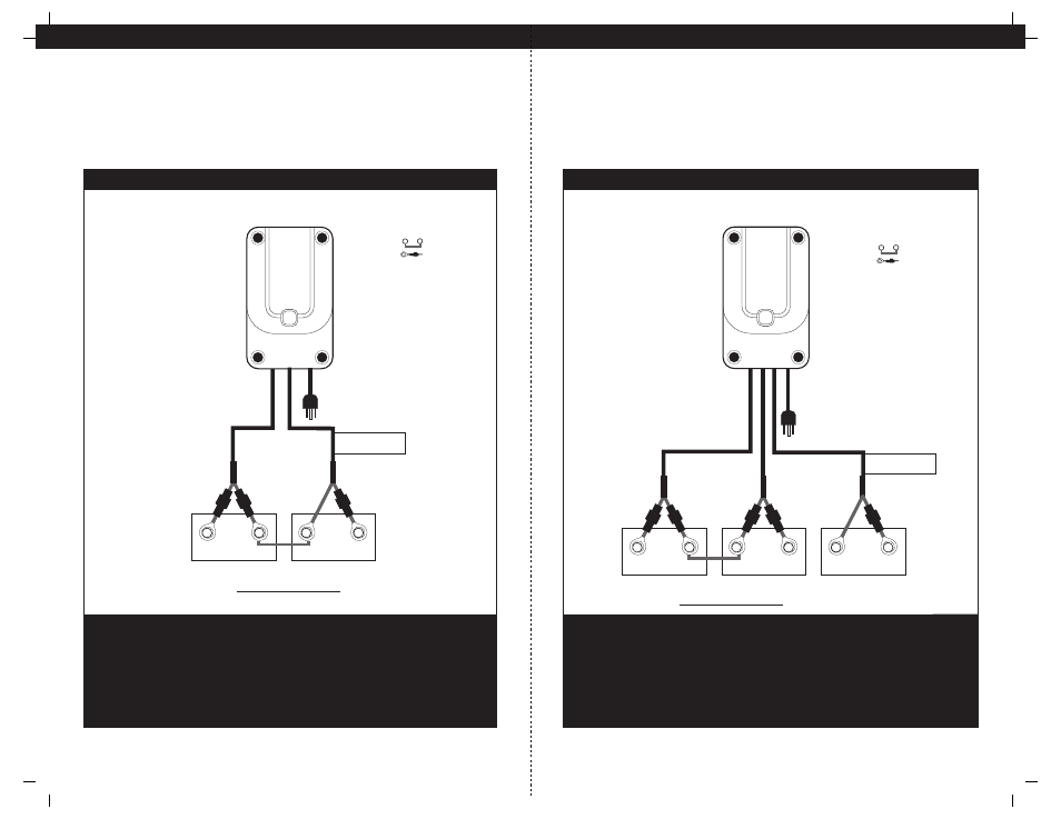
I N S TA L L AT I O N
ProMar1 Wiring Diagrams
12
Triple Output Charger for 3 12V Batteries
Important: The pair of red and black wires in 1 cable jacket MUST GO TO THE SAME 12VDC battery.
24 VDC Trolling Motor Battery Configuration with (2) 12 VDC Batteries Connected
with a Series Jumper Plus Dedicated 12 VDC Engine Start Battery
ProMar1
5/5/3
Output 3
AC po
wer
Output 2
Output 1
Indicates Jumper Series
Note:
Indicates Fuse
When connecting each jacketed battery charger cable, make sure it is connected
to only one 12 VDC battery and observe the polarity and color of all connections:
Red Wire = + (Positive) Battery connection
Black Wire = - (Negative) Battery connection
The black wire can never be connected to a terminal with red wires. Only black.
Installation
12 VDC Engine
Crank Battery
Two 12 VDC Batteries connected with a series
jumper for a 24 VDC Trolling Motor
Top View
of Battery
red
black
+
_
red
black
red
black
Cable 1
Bat 1
Bat 2
Bat 3
Cable 2
Cable 3
For Engine Battery use
this Bank Cable Only
+
_
+
_
I N S TA L L AT I O N
ProMar1 Wiring Diagrams
11
Dual Output Charger for 2 12V Batteries
Important: The pair of red and black wires in 1 cable jacket MUST GO TO THE SAME 12VDC battery.
Top View
of Battery
red
black
+
_
red
black
+
_
Bat 2
Bat 1
Cable 2
Cable 1
Indicates Jumper Series
Note:
Indicates Fuse
Dedicated 24 VDC Trolling Motor Battery Configuration
with (2) 12 VDC Batteries Connected with a Series Jumper
Two 12 VDC Batteries connected with a series jumper
for a 24 VDC Trolling Motor
For Engine Battery use
this Bank Cable Only*
*Note: When an engine crank battery is not being used this bank cable can be connected as shown for a 24 VDC trolling motor.
When connecting each jacketed battery charger cable, make sure it is connected
to only one 12 VDC battery and observe the polarity and color of all connections:
Red Wire = + (Positive) Battery connection
Black Wire = - (Negative) Battery connection
The black wire can never be connected to a terminal with red wires. Only black.
Installation
Output 2
AC po
wer
Output 1
ProMar1
5/5